Section 7-Flywheel, Cronkshaft,
and
Main Bearings
25
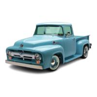
SCRATCHES
DIRT
IMe'Eo(
)Eo
INTO BEARING
MATERIAL
SCRATCHED
BY
DIRT
LACK OF
OIL
IMPROPER SEATING
RADIUS
RIDE
fATIGUE
FAILURE
6491
Fig.
33-Bearing
Failures-Typical
result in crankshaft failure, while too large a radius will
result in bearing failure.
CAUTION:
Never
grind
journals
or
crankpin.
in
e%ce
••
of
O.
030·in
ch
unde"ize.
After
grinding
,
chamfer
the
oil holes,
then
polish
the
pin
or
journal
with
No.
320
grit
polishing
cloth
and
engine oil. Crocus
cloth
may
also
be
used
as a polishing
agent.
c.
Main
Bearings.
The
insert-
type
main
bearings are
select
fit
They
are
available for
service
in standard and undersizes for
use
on journals
that
have
been
reground.
The
installation
of
new bearings
must
be
closely
checked to maintain the
proper clearance
between
the
journals and bearing
surfaces.
(1)
INSPECTION
.
Check
the
bearings
for
any
dam·
age or excessi
ve
clearance.
Examples
of
bearing failures
and
th
eir
causes
are
ill
ustrated
in
fig.
33
.
(2)
FITTING
MAIN
BEARINGS
-
PLASTIGAGE
METHOD
.
The
following
procedl!re
applies
to
fitting
main
bearings with
the
engine
either installed
on
a
workstand or in
the
truck.
If
the
bearing
fits
are
to
be
checked
with
the
engine
in
the
truck,
support
th
e
weight
of
the
crankshaft
with
.a
small jack positioned
to
hold
the
crankshaft upward
against
the
block
half
of
the
main
bearings.
Place
the
jack
to
bear against the crankshaft counterweight adjoin-
ing the bearing which is being
checked
for clearance.
The
s
haft
can
also
be
supported
by
a
thin
rubber
pad
b
etwee
n
the
cap insert and
the
journal
of
two
bearings
that are
not
being checked.
Tighten
these
bearing
cap
bolts
ju
st e
nou
gh
to hold
the
crankshaft
up
against
the
upper bearings.
NOTE:
It
i.
nece
..
ary
to
IUpport
the
weight
of
the
crankshaft.
when
checking
main
bearing
clearances
to
prevent
the
weight
of
the
c
rank.haft
from
com·
pressing
the
Plmtigage,
thereby
providing
an
erro·
neous
reading.
Place
a
piece
of
Plastigage,
the
full
width
of
the
bearing,
on
the
bearing
surface
(or
on
the
crankshaft
journal
if
the
engine
is
inverted)
about
Y.·inch off
center.
Install
the
cap
and
tighten
the
bolts
to
specifications.
CAUTION:
Do
not
turn
the
crank.haft
while
the
Plastigage
i.
in
place.
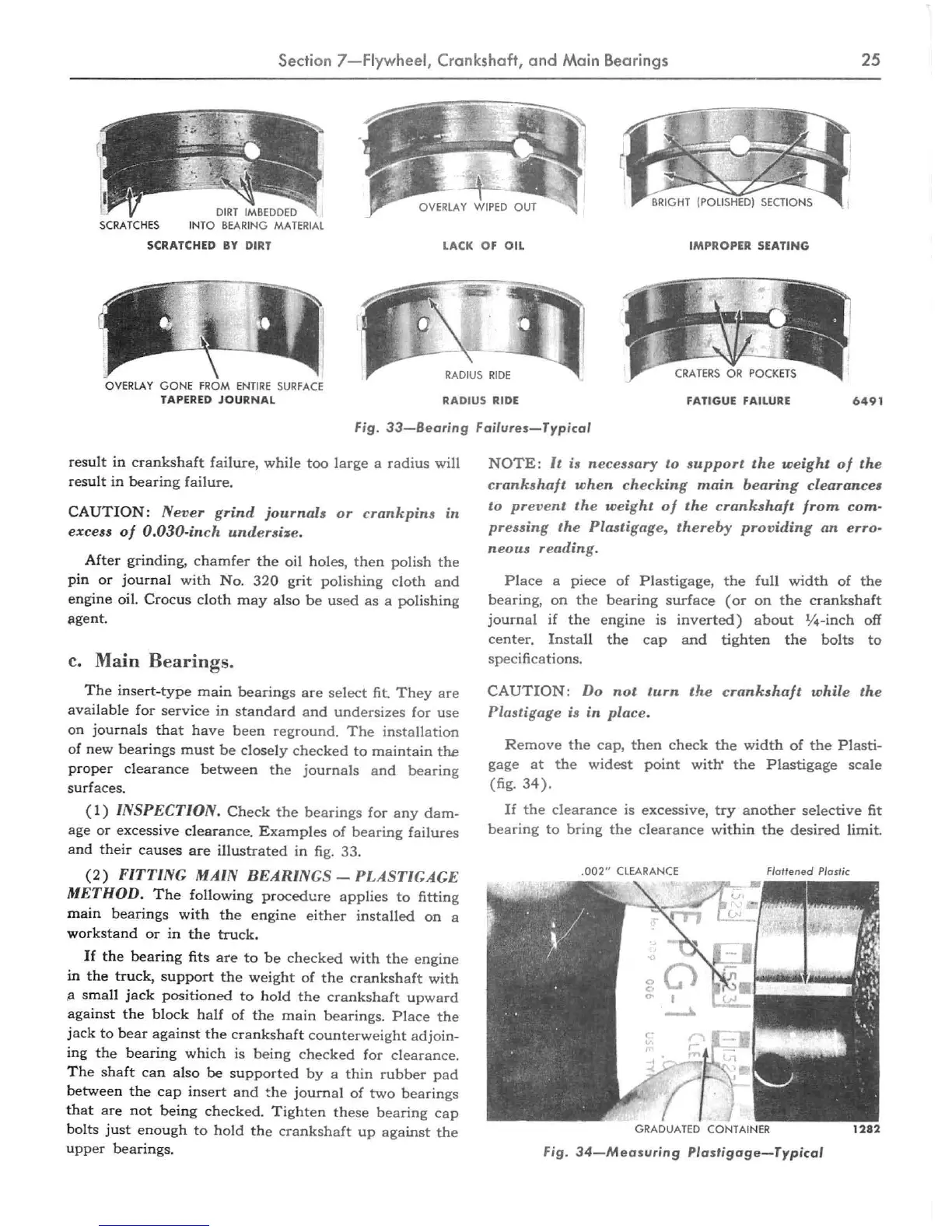
Remove
the
cap,
then
check
the
width
of
the
Plasti·
gage
at
the
widest
point
with'
the
Plastigage
scale
(fig.
34).
If
the
clearance is
excessive,
try
another
selective
fit
bearing
to
bring
the
clearance
withi
n
the
desired
limit.
.002"
CLEARANCE
Flattened
Plastic
GRADUATED
CON
TAINER
1282
Fig.
34-Measuring
Plastigage
- Typical
 Loading...