14
OPERATING MODE: Regulation of pulse current I
1
using
TR 52mc remote-control pedal unit
- It is particularly advantageous with manual TIG welding in
cases where it is necessary to alter the welding pulse current
during the welding operation. (Where the welder is dealing
with materials of different strengths, for example).
- Link the connecting socket on the power source and the
socket
on the remote-control pulsing unit electrically with
the remote control cable.
- A remote control cable of the same type may be used for
linking the remote-control pulsing unit (socket
) to the
remote control pedal unit (socket ).
- Plug in the pug-in connections the right way round, and
screw the coupling ring on as far as possible.
- When the TR 52mc remote-control pedal unit is connected,
the machine automatically switches over to 2-step operation.
- LED indicator blinks up on the power source
- Set desired operating mode with function button
- The appropriate LED indicator , or lights up - oper-
ating mode electrode (LED indicator ) is possible
- The mean welding-current amperage is indicated on dis-
play A. - No "Hold" function
- To initiate the ignition process, gently step on the pedal.
- The level of the start arc current, the pulse current I
1
and the
final crater current can also be controlled from the pedal.
- The base current I
2
that is set using the dial on the TR
50mc is a constant percentage of the value of the pulse
current I
1
.
- When the welder takes his foot right off the pedal, the
welding current is switched off, thus interrupting the welding
operation.
- Gas post-flow time elapses.
Press pedal ð "Welding ON"
Release pedal ð"Welding OFF"
Fig.15 Functional sequence in pulsed-arc mode, using TR52mc (2-step)
I
1
I
2
I
t
Start of cycle
Gas pre-flow time
Pulsed current rise,
controlled from pedal
Gas post-flow time
End of welding
Welding in pulsed-arc
mode: I
1
- I
2
Arc ignition with
minimum current
Pulsed current drop,
controlled from pedal
f
(Hz)
Release torch trigger
Press and hold torch trigger
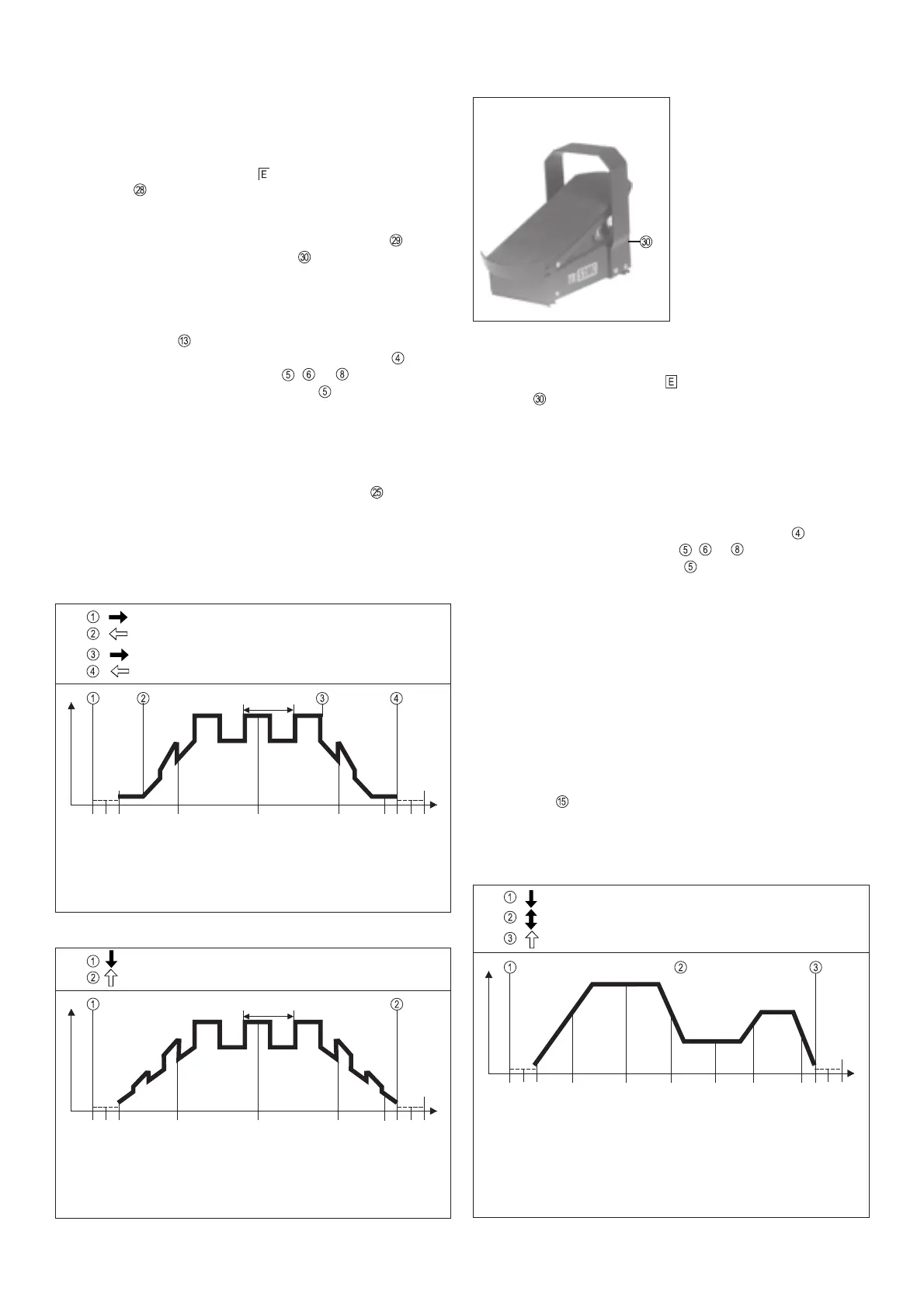
Fig.14 Functional sequence in pulsed-arc mode, using TR 50mc (4-step)
I
S
I
1
I
2
I
t
Press and hold torch trigger
Release torch trigger
I
E
Start of cycle
Gas pre-flow time
Pulsed current rise via
upslope
Gas post-flow time
End of welding
Welding in pulsed-arc
mode: I1, I2 / f /
duty cycle
Arc ignition with start-
arc current I
S
Pulsed current drop
via downslope
Crater-fill current
f
(Hz)
Crater-fill current
TR 52MC REMOTE CONTROL PEDAL UNIT
Connecting the remote control unit:
- Link the connecting socket on the power source and the
socket on the remote-control unit electrically with the remote
control cable.
- Plug in the plug-in connections the right way round, and screw
the coupling ring on as far as possible.
Functional description:
- When the TR 52mc remote-control pedal unit is connected, the
machine automatically switches over to 2-step operation.
- Set desired operating mode with function button
- The appropriate LED indicator , or lights up - operating
mode electrode (LED indicator ) is possible
- The mean welding-current amperage is indicated on display A.
- No "Hold" function
- Gas pre-flow time and gas post-flow time are set directly at the
power source.
- To initiate the ignition process, gently step on the pedal.
- The level of the start arc current, the main current I
H
and the final
crater current can also be controlled from the pedal.
- When the welder takes his foot right off the pedal, the welding
current is switched off, thus interrupting the welding operation.
Gas post-flow time elapses.
Limitation of main current
If the maximum welding current value is set internally on the main
current I
H
dial then the remote control pedal may be depressed
to its full extent without the main welding current exceeding the
pre-set value. This has the advantage that the selected current
range is covered by one complete depression of the foot pedal.
Due to the fact that workpie-
ces are often awkwardly
shaped, it is often necessary
to alter the amperage in the
course of the welding operati-
on. (e.g. repairing the edges
of tools, improvements to cut-
ting dies).
The TR52mc pedal remote-
control unit is designrd to be
used for jobs such as these.
Fig.16 TR 52mc remote control pedal unit.
Press pedal ð Welding "ON"
Change in current, controlled from pedal
Release pedal ð Welding "OFF"
Fig.17 Functional sequence using TR 52mc remote-control pedal unit
I
H
I
t
Start of cycle
Gas pre-flow time
Current-rise,
controlled from pedal
Gas post-flow time
End of welding
Current-drop,
controlled from pedal
Arc ignites with minimum
current
Max. welding current
limited by internal main-
current dial
Reduced welding current
Current rises again,
controlled from pedal
Crater-fill
current
 Loading...