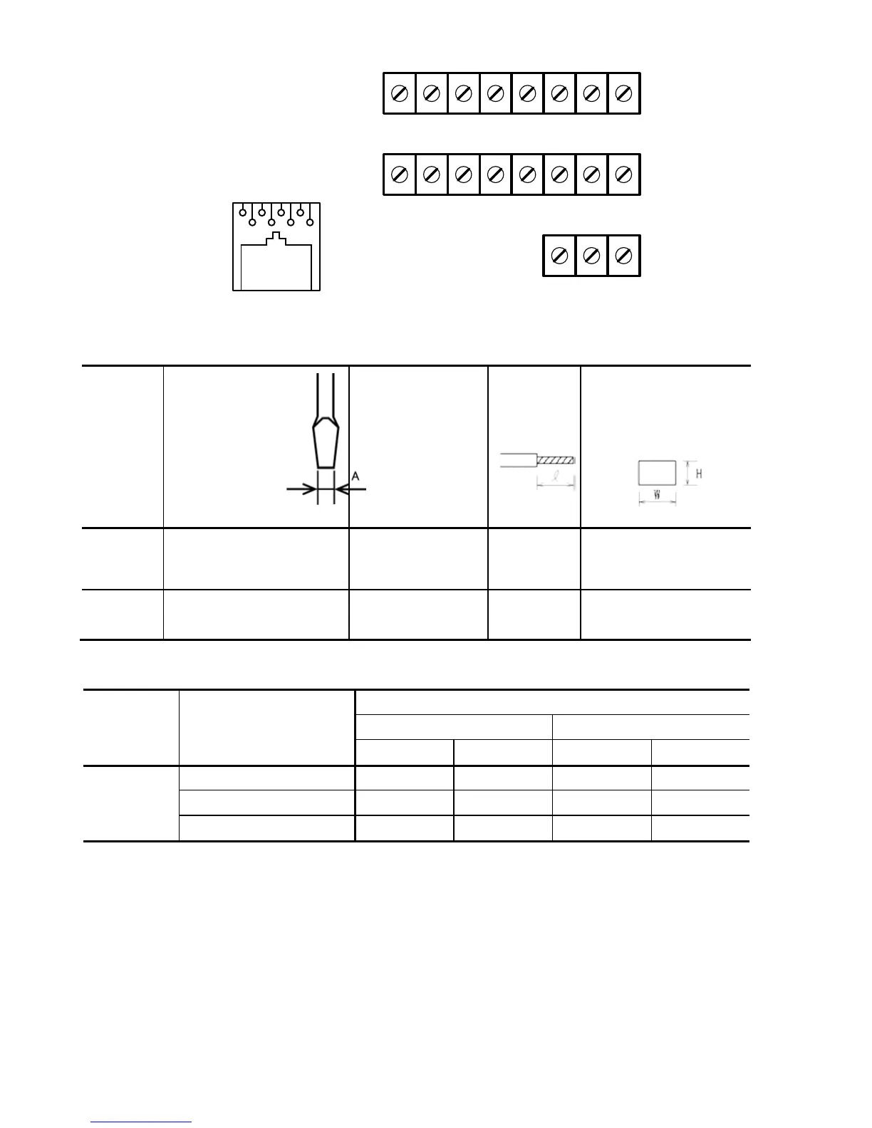
(2) Arrangement of the control circuit terminals (common to all FVR-Micro models)
Y1 Y1E FMA C1 PLC X1 X2 X3
DX+ DX- 13 12 11 FWD REV CM
30A 30B 30C
8 7 6 5 4 3 2 1
1 : 5V
2 : Ground
3 : NC
4 : DX-
5 : DX+
6 : NC
7 : Ground
8 : 5V
Screw size : M2.5 Tightening torque : 0.4Nm
Table 3.2 Control Circuit Terminals
Terminal
symbol
Screwdriver
(Shape of
tip,
B x
A)
Thickness of tip: B
Allowable wire size
Ferrule
terminal*
Opening dimension
in
the terminal
block
First row in
the box
Flat screwdriver
(0.6 x 3.5 mm)
AWG22 to AWG14
(0.34 to 2.1 mm
2
)
4.5 to 5 mm 5 (W) x 2.5 (H) mm
Other than
the above
Flat screwdriver
(0.6 x 3.5 mm)
AWG24 to AWG14
(0.25 to 2.1 mm
2
)
5 to 6 mm 2.3 (W) x 2.5 (H) mm
Table 3.3 Recommended Ferrule Terminals
Screw size Wire
size
Type
(216- )
With insulated collar Without insulated collar
Short type Long type Short type Long type
M2 or M2.5
AWG22 (0.34 mm
)
221
201
121
101
AWG18 (0.75 mm
2
)
The length of bared wires to be inserted into ferrule terminals is 5.0 mm or 8.0 mm for the short
or long type, respectively.
The following crimping tool is recommended: Variocrimp 4 (Part No. 206-204).
 Loading...


