3.3 Recommended wire sizes
Table 2.6 lists the recommended wire sizes. The recommended wire sizes for the main circuit
terminals for an ambient temperature of 50°C are indicated for two types of wire: HIV single wire (for
the maximum allowable temperature 75°C).
Table 3.4 Recommended Wire Sizes
Power supply
voltage
Nomi-
nal
applied
motor
(kW)
Inverter type
*1
Recommended wire size (mm
2
)
Control
circuit
Main circuit power
input
[L1/R, L2/S, L3/T]
[L1/L,
L2/N]
Grounding
[ G]
Inverter
output
[U, V, W]
Braking
resistor
[P, DB]
w/o DCR
Three-phase
400 V
0.4
FVR0.4AS1S-4
2.0(2.0)
0.5
0.75
FVR0.75AS1S-4
FVR3.7AS1S-4
Single-phase
200 V
FVR0.4AS1S-7
2.0(2.0)
2.0(2.0)
2.0(2.5)
2.2
FVR2.2AS1S-7
5.5(5.5)
*1 Use crimp terminals covered with an insulated sheath or insulating tube. Recommended wire sizes are for
HIV/IV (PVC in the EU).
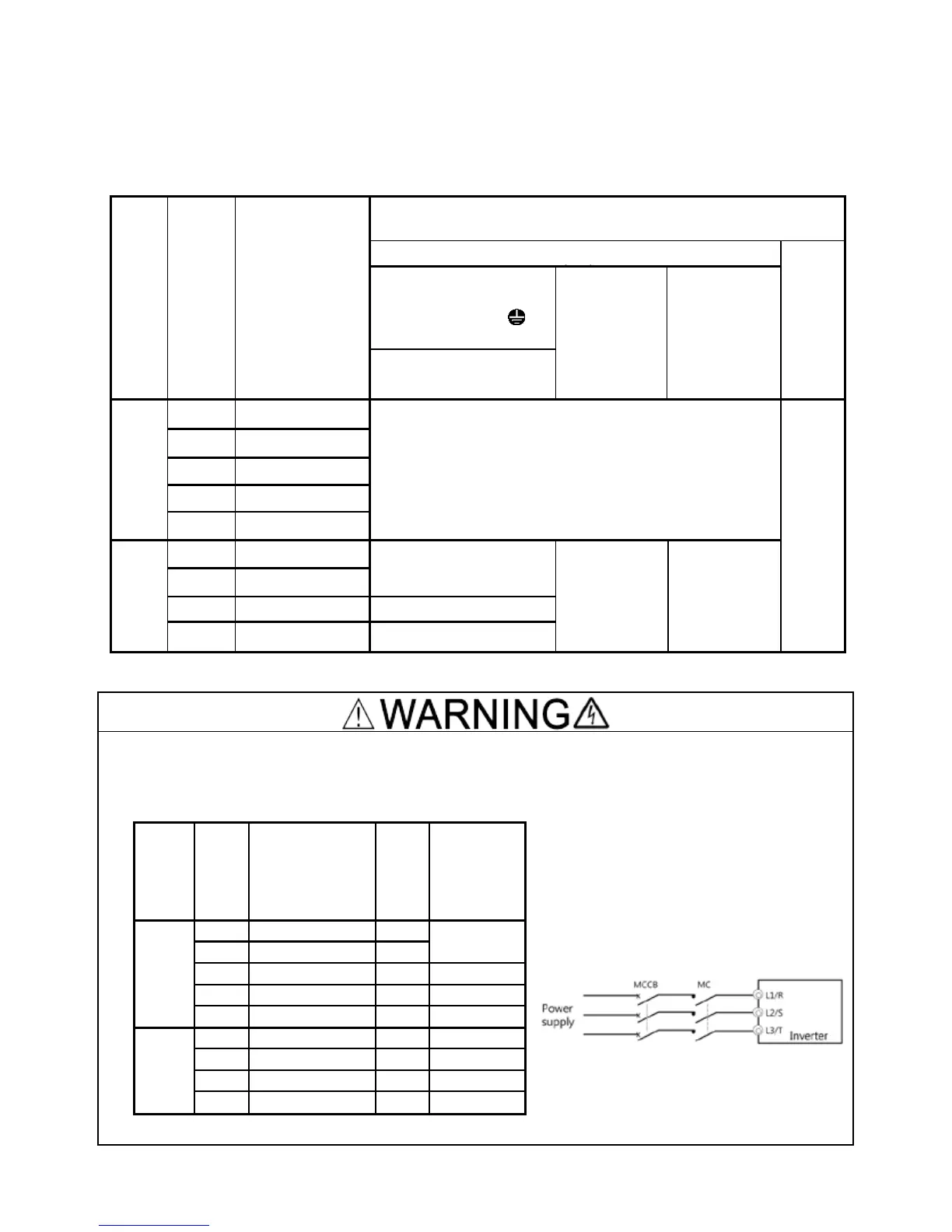
To prevent the risk of hazardous accidents that could be caused by damage of the inverter,
install the specified MCCB in the supply side (primary side) according to the following tables.
- Breaking capacity: Min. 10 kA
- Rated voltage: Min. 500 V
Power
supply
voltage
(A)
Rated
Current(A)
of MCCB
(w/o DCR)
Three-
phase
400 V
 Loading...


