Inverters Communication Error
YES
NO
OK
OK
Outdoor unit Main PCB
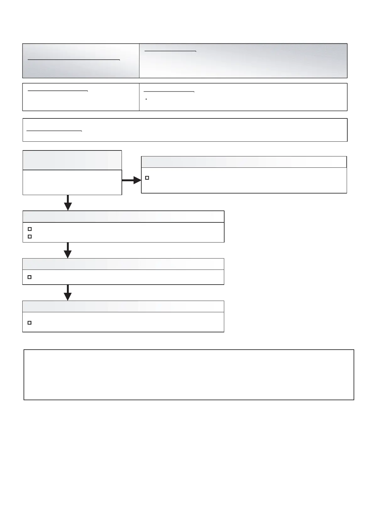
Check Point 2 : Check the main PCB to Inverter PCB wiring
Connector connection state check
Cable open check
Check Point 3 : Check Main PCB
Chack Main PCB. (Refer to "Servise Parts Information 3, 4")
1. Noise 2. Main PCB to Inverter PCB wiring connection defective
3. Main PCB defective 4. Inverter PCB defective
Check Point 4 : Replace Inverter PCB
Replace Inverter PCB.
Check if ground is connection correctly or there are no related cables near the
power line.
Check Point 1-1 :
Turn the power on again
Error displayed again?
Check Point 1-2 : Noise
Communication not received from Inverter PCB for 10 seconds or more
Indoor Unit : Operation LED 9 times Flash, Timer LED 15 Times Flash,
Filter LED Continuous Flash.
Outdoor Unit : E. 6 2. 6
Error Code : 9 U / 6 2
Trouble shooting 29 E62. 6
Indicate or Display:
Detective Actuators:
Detective details:
OUTDOOR UNIT Error Method:
Forecast of Cause :
Caution
By changing of DIP SW 4-2 to ON, the Back-up operation can start when the active outdoor unit exists on the multi outdoor unit connection.
(Stand alone outdoor unit is impossible)
The following conditions will be concerned in use of back-up operation. (Please do not use the system with back-up operation for long time.)
- The operating compressor life time becomes shorter.
- The operating performance may drop due to the limited active compressor(s).
- The compressor may stop frequently by protection controlling.
*In order to keep the operating capacity, the release of the Low noise mode setting might be necessary.
04-38
 Loading...