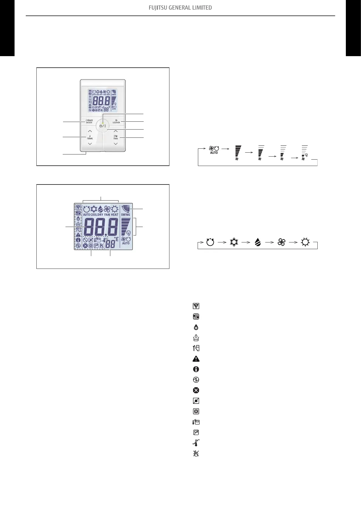
14-13. Simple remote controller (UTY-RSRY and UTY-RHRY:
Optional parts)
¢
Overview
Display panel
a LED lamp
Lights during operation.
b Louver button
Adjusts the airflow direction.
c START/STOP button
Starts and stops operation.
d FAN control button
Switches the fan speed as follows:
e Room temperature sensor (inside)
Senses ambient temperature of unit.
f Set temperature button
Selects the setting temperature. (18—30 °C [COOL], 10—
30 °C [HEAT])
g Operation mode button*
1
Switches the operation mode as follows:
Auto
Cool
Dry Fan Heat
*
2
*
3
*
4
h Operating mode indicator
i Airflow direction indicator
j FAN speed indicator
k Remote controller address indicator
l Status icons
Mode mismatch
Filter sign *
5
Defrost operation
Oil recovery operation
Under maintenance
Error
Special state
Conducting electricity
Emergency stop
Operation controlled
Forced stop
Remote controller sensor is enabled *
5
Central controlled
Setting temperature range is enabled
Operation prohibited
m Set temperature
Indicates indoor unit address. *
6
*
1
: Available only for UTY-RSR*.
*
2
: Not available for a heat pump model unless it is set up as
an administrative indoor unit.
*
3
: Not available for a heat pump model.
*
4
: Not available for a cooling-only model.
*
5
: Set the function setting of the indoor unit accordingly.
*
6
: During address display mode.
- 294 -
14-13. Simple remote controller (UTY-RSRY and UTY-RHRY: Optional parts)
14. Remote controller
4-5 UNIT
MULTI-SPLIT TYPE
4-5 UNIT
MULTI-SPLIT TYPE
 Loading...