3.2
!
Scanner Unit
14
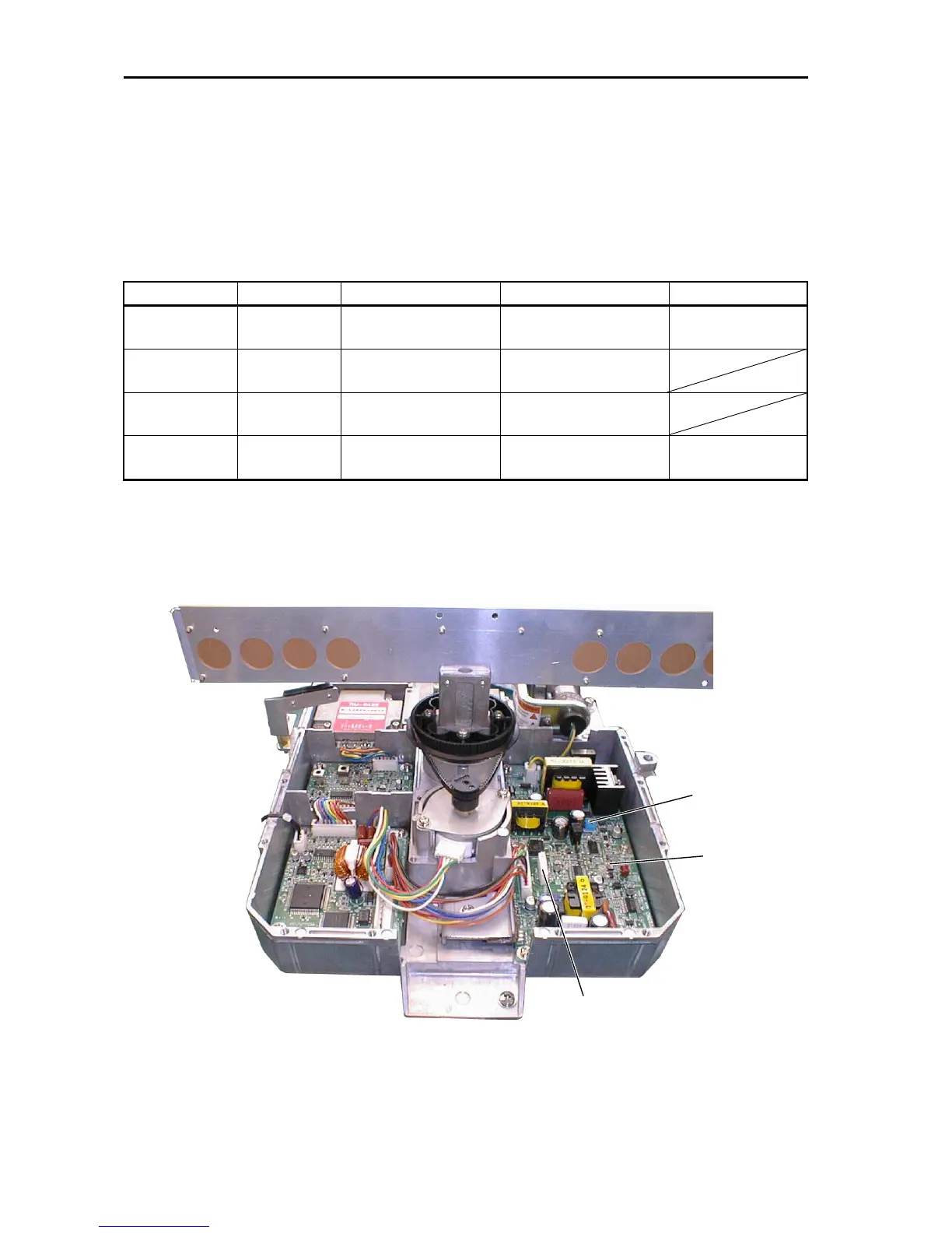
3.2 Scanner Unit
Voltage check
Open the radome, and measure each voltage with the modulator cover removed.
Table 3-2
Item Setting Check point Rating Adjuster
"
12 V
ST-BY
TP804#3
#"$%
TP804#4
#&$
11.9
'
12.1 Vdc
VR801
"
8 V
heater volt.
ST-BY
TP804#6
#"$%
TP804#4
#&$
7.8
'
8.2 Vdc
TX-HV
(divided)
TX(Note)
(3NM)
TP804#7
#"$%
TP804#4
#&$
8.5
'
9.35 V
Magnetron
current
TX(Note)
(3NM)
TP804#5
#"$%
TP804#4
#&$
2.8
'
3.6 V
VR851
Note)
To transmit with scanner rotation suspended, turn on the power while pressing and
holding down the%&'key. After one minute, the radar is in transmission mode.
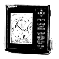
Figure 3-2. Test points on MD Board
VR851
VR801
TP804
 Loading...