Chapter 2. Block Description
3
2.1 General
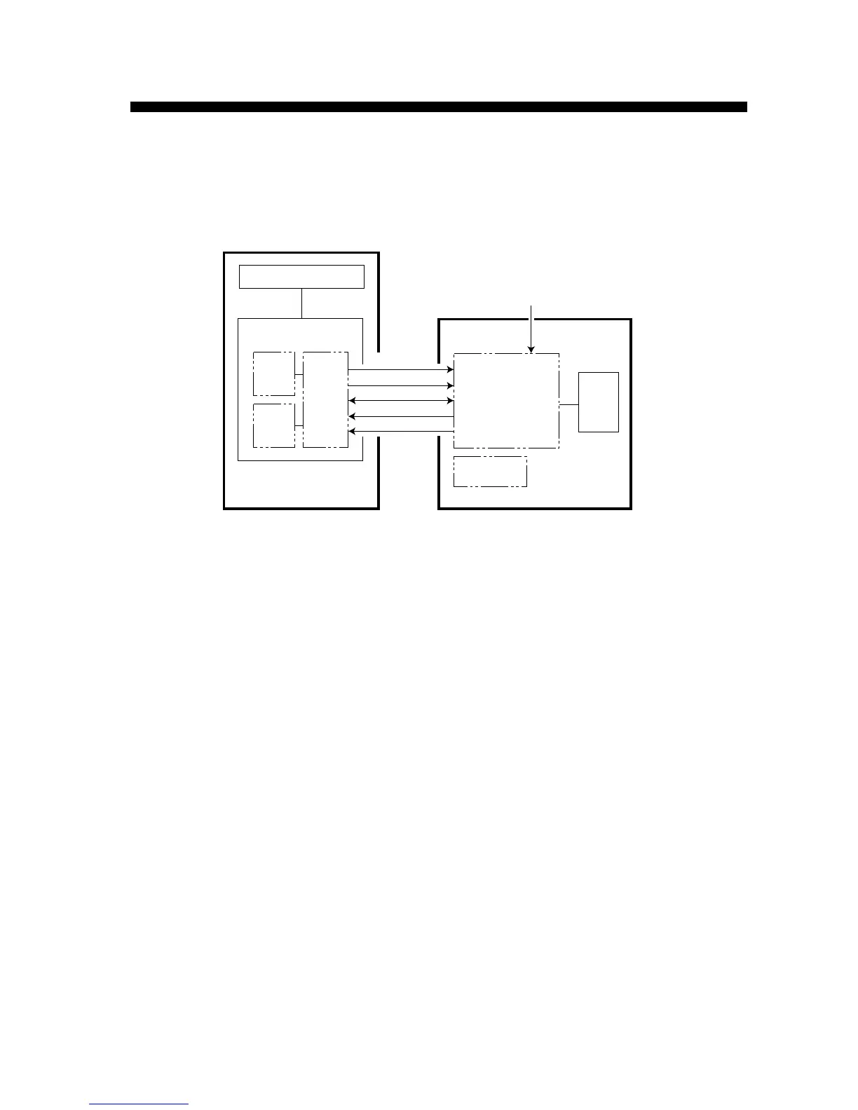
The CPU on the DU board of the display unit communicates with the CPU on the SD board of
the scanner unit in RS-422 format.
Figure 2-1. Simplified Block Diagram
The trigger pulse from the DU board is modulated at the MD board to oscillate the magnetron.
The echo received by the antenna is amplified by the IF amplifier and is fed to the DU board as a
video signal. The DU board converts the analog signal to digital signal and processes to display
it on the LCD.
Bearing pulse (BP) and heading signal (HD) are generated in the scanner unit and received by
the DU Board in the display unit.
Radiator
Transceiver
Display Unit
PNL Board
Scanner Unit
Ship’s mains
DU Board
LCD
Signal processor
& power supply
Video signal
BP/HD
Communication (H.C)
Trigger
Ship’s mains (H.C)
INT
Board
MD
Board
IF
Board
 Loading...