EasyManua.ls Logo

Furuno 1622 User Manual

Furuno 1622
42 pages
To Next Page IconTo Next Page
To Previous Page IconTo Previous Page
Page #4 background imageLoading...
Page #4 background image
Chapter 1. General
1
1.1 Display Unit
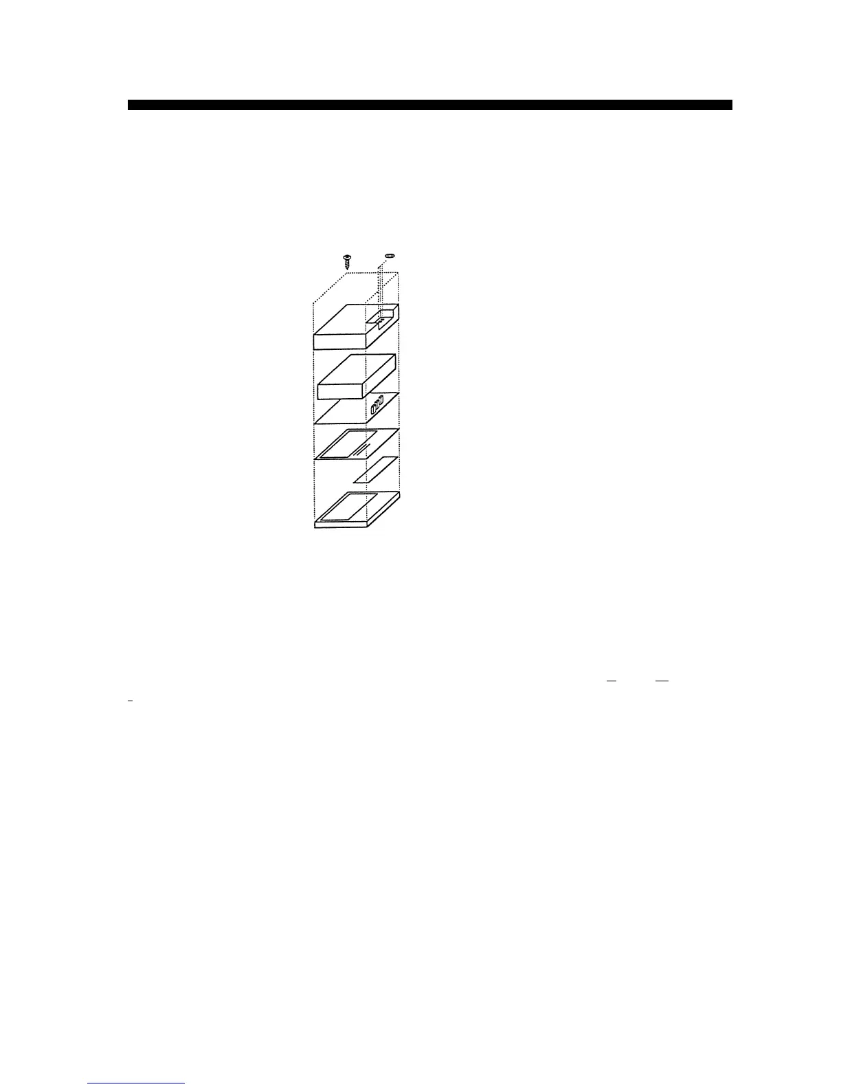
All parts are sandwiched together and fastened by four screws and three connector fixing nuts
from the rear side.
Figure 1-1. Construction of Display Unit
Protection against EMI
Many radars use conductive paint inside their covers to protect against EMI (Electro Magnetic
Interference). This model, however, is not painted, but has a shield cover over the DU board for
protection against EMI.
Waterproofs
The display unit conforms to the IEC standard IPX5; namely, waterproof against water jets. Even
the small hole to the right of the arrow keys, which is where the aural alarm is released, is
waterproof. A “breathing sheet” between the panel cover and the buzzer allows air to pass and
prevents water from being drawn into the enclosure during atmospheric pressure changes.
Resin cover
Shield cover
DU Board
LCD Display
PNL pcb
Panel cover

Other manuals for Furuno 1622

Questions and Answers:

Furuno 1622 Specifications

General IconGeneral
Display TypeLCD
Power Output2.2 kW
Rotation Speed24 RPM
Power Supply12/24 V DC
Screen Size6 inches
Range24 nautical miles
Weight12 kg
Display Size6 inches
Antenna Length15 in or 18 in
Frequency9.4 GHz

Summary

Chapter 1. General

1.1 Display Unit

Details the construction, EMI protection, and waterproofing of the display unit, including its components.

1.2 Scanner Unit

Describes the components of the scanner unit and the antenna cable's communication lines.

Chapter 2. Block Description

2.1 General

Explains the communication protocol (RS-422) between the display and scanner units.

2.2 Display Unit

Outlines the key features and provides a block diagram of the display unit's internal components.

2.3 Scanner Unit

Lists the features of the scanner unit and presents its main block diagram.

2.4 Functions of Each Circuit board

Details the functional roles of the PANEL board, DU board, and INT board within the system.

Chapter 3. Adjustment

3.1 Display Unit

Covers voltage checks and identifies test points on the DU Board for adjustment.

3.2 Scanner Unit

Details voltage checks and identifies test points on the MD Board for scanner unit adjustment.

Chapter 4. Maintenance

4.1 Maintenance Parts

Lists essential parts for maintenance, including part numbers and remarks.

4.2 Replacement of Major Parts

Provides step-by-step instructions for disassembling and reassembling major components.

4.3 How to change system program

Explains the procedure for updating the unit's system program by replacing the ROM.

Chapter 5. Troubleshooting

5.1 Maintenance Menu

Details how to access and utilize the maintenance menu for system diagnostics.

5.2 Error Messages

Lists and explains common error messages and their potential causes.

5.3 Troubleshooting Matrix table

Offers a diagnostic table to identify faulty PCBs or blocks based on observed symptoms.

5.4 Test points on Each Board

Specifies test points on various boards with their expected readings and check items.

Related product manuals