2. WIRING
2-9
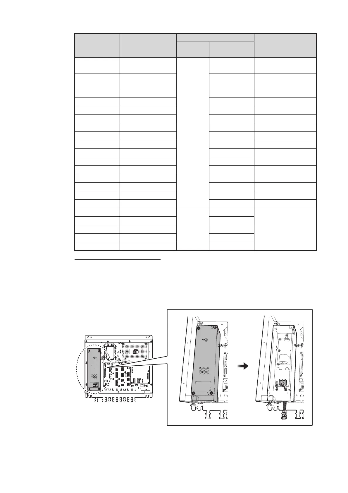
Connection of power cable
Remove the four screws on the cable cover inside the distributor unit. Set the power
cable from ship’s Mains on the no.1 cable entrance, referring to the "Cable
entrance" on page 2-8 and fasten the cable with two cable ties supplied locally. The
core should be connected to CN1 terminal as follows.
No. of cable
entrance
Signal
Printed board
Remarks
Type
Connector
no.
2 TRX POWER 65P6110
(DST)
CN2 Power to transceiver
unit
3 TRX CN3 Signal from trans-
ceiver unit
4 SUB DISP1 CN4
5 DISP CN5
6 SUB DISP2 CN6
7 IEC61162OUT3 CN7
8 IEC61162IN1 CN8
9 IEC61162IN2 CN9
10 IEC61162OUT1 CN10
11 IEC61162OUT4 CN11
12 DIMMER CN12
13 POWER FAIL CN13
14 IEC61162OUT2 CN14
15 EXT KP IN CN15
16 LAN CN16
—USB CN17
18 SYSTEM FAIL
65P6111
(LIF)
CN18
Option
19 ANA DISP1 CN19
20 ANA DISP2 CN20
21 ANA DISP3 CN21
22 ANA DISP4 CN22
CN1
 Loading...