EasyManua.ls Logo

Furuno DS-8530 User Manual

Furuno DS-8530
94 pages
To Next Page IconTo Next Page
To Previous Page IconTo Previous Page
Page #66 background imageLoading...
Page #66 background image
3. ADJUSTMENTS
3-22
5. Select [START SETTING] to show the confirmation message "START SETTING
OK?". Then select [YES] to start setting. To stop setting, press the MENU key to
go back to the [SERVICE] menu.
6. Set the offset value in the [STEP1 OFFSET] field so that the needle of the analog
display unit will be “0 kn”, and click [NEXT]. The setting range is -4.9 to 4.9 kn. To
stop setting, press the MENU key to go back to the [SERVICE] menu.
For example, when the analog display unit indicates 2 kn, set “2” (kn) on this win-
dow so that the analog display unit indicates 0 kn.
7. Set the offset value in the [STEP2 OFFSET] field so that the needle of the analog
display unit will be “10 kn”, and click [OK] to complete setting. The setting range
is -4.9 to 4.9 kn. To stop setting, press the MENU key to go back to the [SERVICE]
menu.
For example, when the analog display unit indicates 9 kn, set “-1” (kn) on this win-
dow so that the analog display unit indicates 10 kn.
Selected analog portSelected analog port
Selected modeSelected mode
2. 0 0
Question and Answer IconNeed help?

Do you have a question about the Furuno DS-8530 and is the answer not in the manual?

Furuno DS-8530 Specifications

General IconGeneral
BrandFuruno
ModelDS-8530
CategoryMarine Equipment
LanguageEnglish

Summary

SAFETY INSTRUCTIONS

Safety Precautions and Warnings

Details general safety warnings, cautions, and specific precautions for equipment installation and operation.

EQUIPMENT LISTS

1. MOUNTING

1.1 Display Unit Mounting

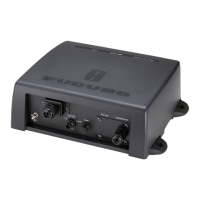
Installation considerations and methods for the Display Unit.

1.4 Transducer Mounting

Critical guidance on transducer installation for optimal system performance.

2. WIRING

2.2 Precautions for Cable Installation

Guidelines for proper cable routing and installation to avoid interference and ensure safety.

2.7 Grounding

Guidelines for proper grounding to prevent interference and ensure safety.

3. ADJUSTMENTS

Transducer Initial Setting

Steps for setting transducer type and cable length during initial setup.

Display Unit Initial Setting

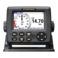
Guides on setting up the display unit, including language and unit settings.

3.1 [EQUIPMENT] Sub Menu

Details options within the [EQUIPMENT] sub menu for transducer and other settings.

APPENDIX 2 DIGITAL INTERFACE

APPENDIX 3 CALIBRATION

Calibration from the Speed Trial

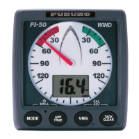
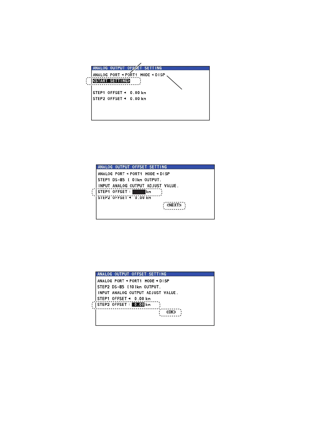
Describes how to perform calibration using speed trial tests for accurate speed display.

INTERCONNECTION DIAGRAM

Related product manuals