1. INSTALLATION
1-7
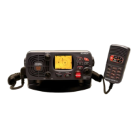
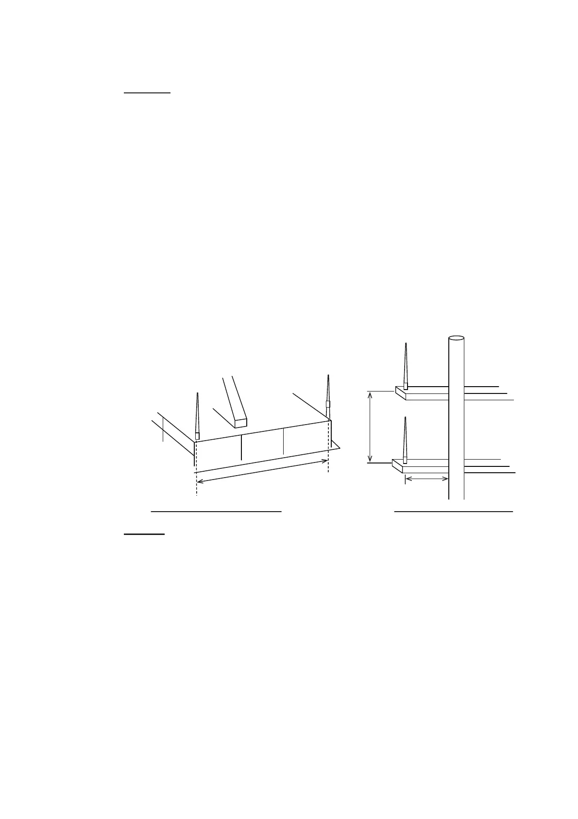
1.6 VHF Antenna (option)
Location
The location of the VHF antenna should be carefully considered. It may be necessary
to relocate the VHF radiotelephone antenna to minimize interference effects. To min-
imize interference effects, the following guidelines apply:
• Select a location out of the radar and inmarsat beams. Those beams will obstruct
or prevent reception of the AIS signal.
• The VHF antenna should be placed in an elevated position that is as free as possi-
ble with a minimum of 0.5 meters in the horizontal direction from constructions
made of conductive materials. The antenna should not be installed close to any
large vertical obstruction. The objective for the VHF antenna is to see the horizon
freely through 360 degrees.
• There should not be more than one antenna on the same plane. The VHF antenna
should be mounted directly above or below the ship's primary VHF radiotelephone
antenna, with no horizontal separation and with a minimum of 2.8 meters vertical
separation. If it is located on the same plane as other antennas, the distance apart
should be at least 10 meters.
Cabling
• The cable should be kept as short as possible to minimize signal attenuation. Co-
axial cables equal to or better than 5D-2V are recommended.
• All outdoor-installed connectors on coaxial cables should be fitted with preventive
isolation such as vulcanizing tape to protect against water penetration into the an-
tenna cable. Also, apply marine sealant at the antenna base to prevent water intru-
sion from the screw part of the antenna base.
• Coaxial cables should be installed in separate signal cable channels/tubes and at
least 10 cm away from power supply cables. Crossing of cables should be done at
right angles (90 degrees). The minimum bend radius of the coaxial cable should be
5 times the cable's outer diameter.
When coaxial cable 5D-2V (shipyard supply) is used, attach the coaxial plug M-P-5
(shipyard supply) as shown on the next page.
Other VHF antenna
Antenna for AIS
More than 10 m
More than 0.5 m
More than 2.8 m
Horizontal separation distance Vertical separation distance
 Loading...