 Loading...
Do you have a question about the Furuno GPS NAVIGATOR GP-150 and is the answer not in the manual?
| Display Type | LCD |
|---|---|
| Display Size | 4.5 inches |
| Resolution | 320 x 240 pixels |
| Channels | 12 channels |
| Interface | NMEA0183 |
| Operating Temperature | -15°C to +55°C |
| Waterproof Standard | IPX6 |
| GPS Accuracy | 10 m (95%) |
| Update Rate | 1 second |
| SBAS Accuracy | 3 m (95% probability, HDOP ≤ 4) |
Describes operator responsibilities and manual usage, including warnings about incorrect operation.
Instructions for product disposal according to local regulations for industrial waste.
Information on battery disposal methods and symbols for different regions.
Important warnings and cautions for safe operation and potential hazards.
Details about the attached warning label and its meaning.
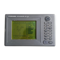
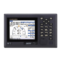
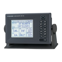
Welcome message and introduction to the GP-150, highlighting FURUNO's quality.
Overview of the GP-150's main capabilities and functions.
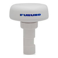
Classification of the system's units based on their environment.
Explanation of the control panel buttons and their functions.
Procedure for powering the unit on and off, including initial startup.
How to modify screen brightness and contrast for optimal viewing.
Choosing different display layouts for navigation data.
Explanation of icons displayed on the unit for status alerts.
Adjusting zoom level on plotter displays for better viewing.
Setting display to north-up or course-up modes.
How to move the cursor on the display.
Moving the displayed track when the ship moves off-screen.
Repositioning the cursor to the center of the screen.
Setting the ship's position to the center of the display.
Controls for saving the ship's track data.
Procedure for deleting stored track data.
Setting how often track points are recorded.
Dividing memory between track and mark storage.
Choosing between True and Magnetic bearing display.
Procedures for adding and deleting marks on the display.
Choosing from available shapes for marks.
Linking marks with lines on the display.
Saving important positions as event marks.
Choosing shapes for event marks.
Marking the Man Overboard position.
How to input and save specific locations as waypoints.
Modifying the details of previously saved waypoints.
Removing waypoints from memory.
Creating and saving sequences of waypoints for navigation.
Removing specific waypoints from a saved route.
Changing a waypoint within a saved route.
Removing entire saved routes.
Procedures for defining the target destination for navigation.
How to abort the current navigation destination.
Removing route flags from the display.
Calculating distances and bearings between locations.
Customizing data fields shown on the data display.
Choosing how position is displayed (Lat/Lon, LOPs).
Simulating unit operation for training purposes.
Setting alarms for reaching waypoints or drifting anchor.
Alert for deviating from the intended course.
Alarms for speed being too high, low, or within a range.
Warning when distance traveled exceeds a set limit.
Alarm for water temperature being too high, low, or within a range.
Alarm for depth being too high, low, or within a range.
Warning when WAAS/DGPS signal is lost.
Configuration settings related to GPS operation and data.
Setting display units for distance, depth, temperature, and altitude.
Adjusting the appearance of marks, text, and screen elements.
Configuring data output and external equipment connections.
Downloading waypoints and routes from a PC.
Configuring settings for WAAS or DGPS beacon receiver.
Viewing GPS satellite and beacon data.
Procedures for resetting GPS and plotter memory to defaults.
Routine checks to keep the equipment in good working order.
Descriptions of error messages and their meanings.
Table of common issues and their solutions.
Procedures for running self-tests on hardware components.
Configuration options for system parameters.
Settings related to the plotter display.
Configuration for measurement units.
Settings for data output on ports 1 and 3.
Settings for data output on port 2.
Input/Output configuration for port 4.
Configuration settings for GPS.
Configuration for WAAS or DGPS beacon receiver.
Settings for Line of Position display.
Procedures for clearing unit memory.
Explains data format, interval, and transmission methods.
Lists input and output NMEA sentences.
Circuit diagrams for data ports.
Map illustrating global time zone differences.
List of geodetic datums and their corresponding codes.
List of replaceable electrical components and their codes.
Explanation of WAAS, EGNOS, MSAS, GAGAN and their satellites.
Definitions of abbreviations and symbols used in the manual.
Technical specifications for the GPS receiver module.
Technical specifications for the display unit.
Details on communication ports and data formats.
Power requirements and specifications.
Operating temperature, humidity, and vibration limits.
Color specifications for the unit.