GEA 71 Installation Manual Page 3-1
190-00303-40 Revision F
3 INSTALLATION PROCEDURE
3.1 Unpacking Unit
Carefully unpack the equipment and make a visual inspection of the unit for evidence of damage incurred
during shipment. If the unit is damaged, notify the carrier and file a claim. To justify a claim, save the
original shipping container and all packing materials. Do not return the unit to Garmin until the carrier
has authorized the claim.
Retain the original shipping containers for storage. If the original containers are not available, a separate
cardboard container should be prepared that is large enough to accommodate sufficient packing material
to prevent movement.
3.2 Wiring Harness Installation
Allow adequate space for installation of cables and connectors. The installer shall supply and fabricate all
of the cables. All electrical connections are made through two 78-pin D-Subminiature connectors
provided by Garmin.
Section 4 defines the electrical characteristics of all input and output signals. Required connectors and
associated hardware are supplied with the connector kit (Refer to Section 2.2.1). See Appendix B for
examples of interconnect wiring diagrams. Construct the actual harnesses in accordance with aircraft
specific approved interconnect diagrams.
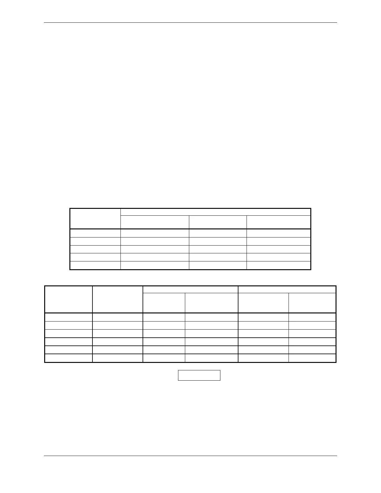
Table 3-1. Pin Contact Part Numbers
78 pin D-Subminiature connector (P701, 702)
Manufacturer
16 AWG
(Power Only)
18-20 AWG
(Power Only)
22-28 AWG
Garmin P/N 336-00044-01 336-00044-00 336-00021-00
Military P/N N/A N/A M39029/58-360
AMP N/A N/A 204370-2
Positronic N/A N/A MC8522D
ITT Cannon N/A N/A 030-2042-000
Table 3-2. Recommended Crimp Tools
18-20 AWG 22-28 AWG
Manufacturer Hand Crimping
Tool
Positioner Insertion/
Extraction Tool
(note 2)
Positioner Insertion/
Extraction
Tool
Military P/N M22520/2-01 N/A M81969/1-04 M22520/2-09 M81969/1-04
Positronic 9507 9502-11 M81969/1-04 9502-4 M81969/1-04
ITT Cannon 995-0001-584 N/A N/A M22520/2-09 274-7048-000
AMP 601966-1 N/A 91067-1 601966-6 91067-1
Daniels AFM8 K774 M81969/1-04 K42 M81969/1-04
Astro 615717 N/A M81969/1-04 615725 M81969/1-04
NOTES
1. Non-Garmin part numbers shown are not maintained by Garmin and consequently are subject
to change without notice.
2. Extracting the #16, #18 and #20 contact requires that the expanded wire barrel be cut off from
the contact. It may also be necessary to push the pin out from the face of the connector when
using an extractor due to the absence of the wire. A new contact must be used when
reassembling the connector.
3. For applications using 16 AWG wire, contact Garmin for information regarding connector
crimp positioner tooling.

 Loading...


