GEA 71 Installation Manual Page 4-5
190-00303-40 Revision F
4.2 Electrical Characteristics
4.2.1 Analog Input Configuration
All analog inputs, except those discussed in Section 4.2.3 are multi-purpose capable and have several
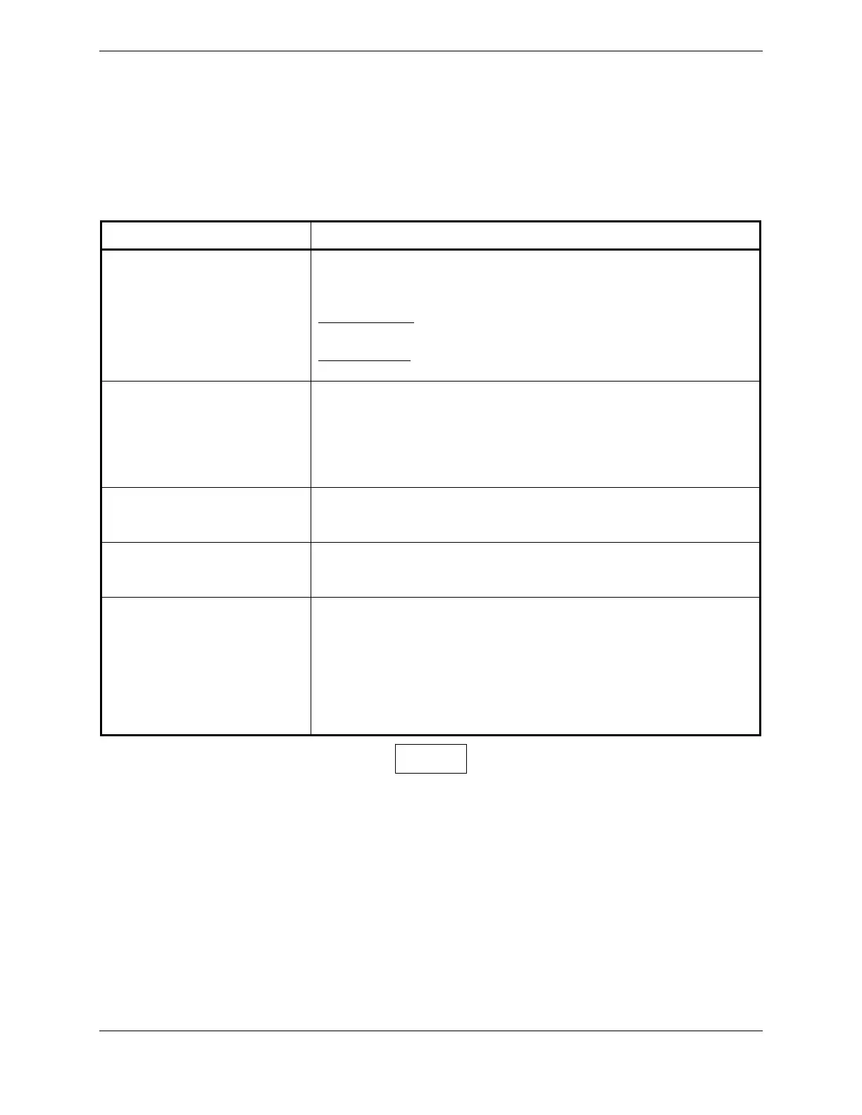
configuration options. Table 4-1 summarizes the configuration options.
Table 4-1. Analog Input Configuration Summary
Configurable Parameter Description/Characteristic
Resistive Divider
Resistive Divider can be enabled or disabled for each analog input.
Enabling & Disabling is achieved via software configuration. See
Section 3.6.
When Disabled
: Hardware scaling is 1:1 and input impedance is
greater than 10 MΩ.
When Enabled
: Hardware scaling is 50:1 and input impedance is
approximately 100 kΩ.
Voltage Measurement Ranges There are six voltage measurement ranges for analog inputs:
• 25 mV, 55 mV, 100 mV, 1 Vdc, 2.5 Vdc, and 5.0 Vdc (Applies
to both 1:1 and 50:1 scaling).
Effective voltage range in 50:1 mode:
• 1.25 Vdc, 2.75 Vdc, 5.0 Vdc, and 50 Vdc.
Bipolar/Unipolar
Each analog input can be configured to measure Bi-Polar (positive
and negative) or Uni-Polar (positive only) voltages. All analog inputs
are differential.
Constant Current Source
Each analog input can be configured to supply a 250 µA constant
current source (CCS) from the positive differential input used to
measure resistive sensors.
Miscellaneous Sensor
Configuration Parameters
• Update Rate
• High Side Current Monitor Feature Enabled/Disabled
• Voltage Translation Equations
• Minimum/Maximum Values for Sensors
• Hysteresis Value
• Digital Filtering Value
If installing an ungrounded thermocouple to an Analog In input, a dc reference must be
added to the LO input. This can be accomplished by adding a resistance of 1 MΩ or less
between ground and the Analog In LO input that the ungrounded thermocouple is
installed on.
NOTE

 Loading...


