GIA 63 Installation Manual 190-00303-05
Page 3-2 Rev. Y
3.2 Wiring Harness Installation
Allow adequate space for installation of cables and connectors. The installer shall supply and fabricate all
of the cables. All electrical connections are made through 44, 62, and 78-pin D subminiature connectors.
Section 4 defines the electrical characteristics of all input and output signals. Required connectors and
associated hardware are supplied with the connector kit.
See Appendix C for examples of interconnect wiring diagrams. Construct the actual harnesses in
accordance with aircraft manufacturer authorized interconnect standards.
1. Non-Garmin part numbers shown are not maintained by Garmin and consequently are subject to
change without notice.
2. Extraction of 16 and 18 AWG contacts requires that the expanded wire barrel be cut off from the
contact. It may also be necessary to push the pin out from the face of the connector when using an
extractor due to the absence of the wire. A new contact must be used when reassembling the
connector.
3. For applications using 16 AWG wire, contact Garmin for information regarding connector crimp
positioner tooling.
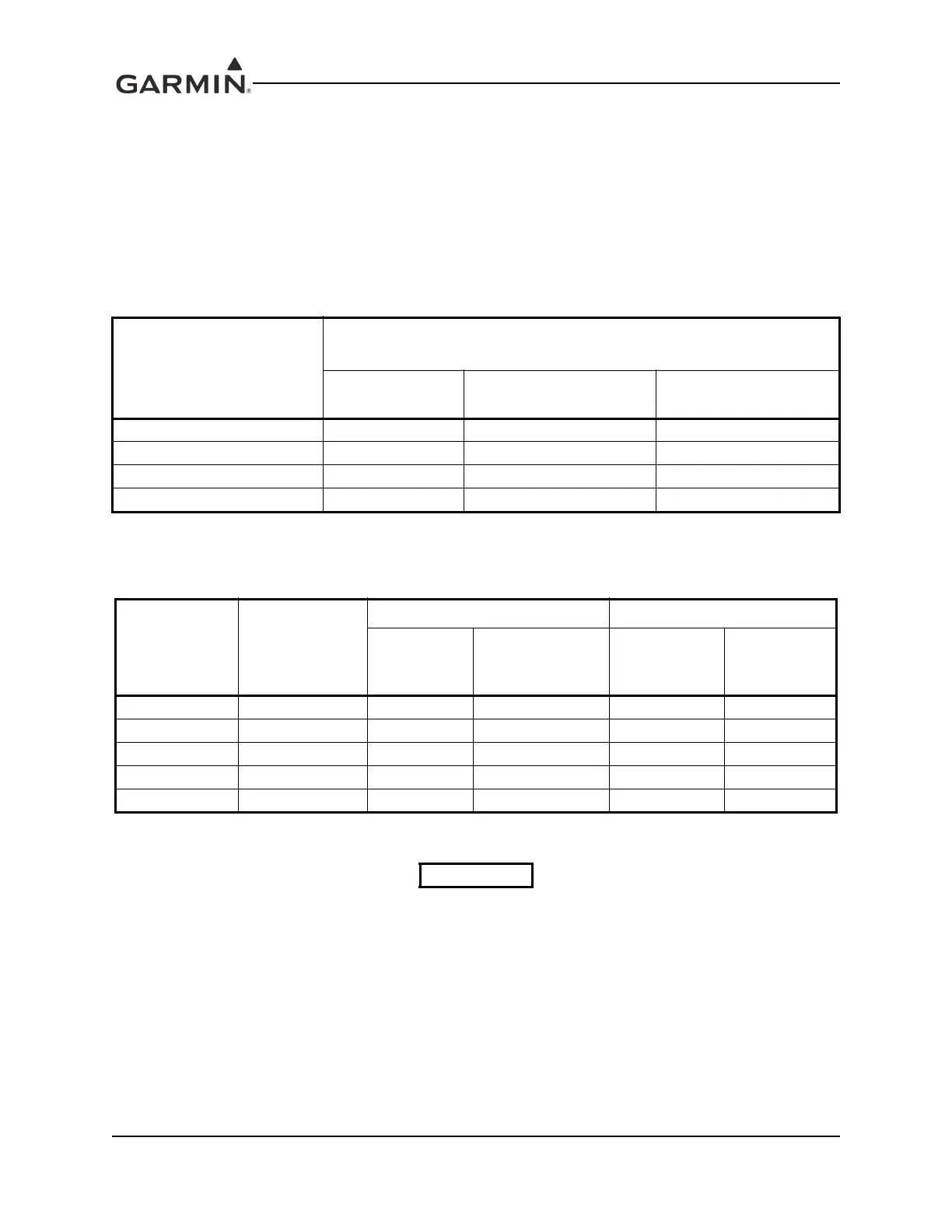
Table 3-1. Pin Contact Part Numbers
Manufacturer
78 pin connectors (P603, 605, 606), 62 pin connectors (P602), 44 pin
connectors (P604 and P601)
16 AWG
(Power Only)
18-20 AWG
(Power Only)
22-28 AWG
Garmin P/N 336-00044-01 336-00044-00 336-00021-00
Military P/N N/A N/A M39029/58-360
AMP N/A N/A 204370-02
Positronic N/A N/A MC8522D
Table 3-2. Recommended Crimp Tools
Manufacturer
Hand
Crimping Tool
18-20 AWG 22-28 AWG
Positioner
Insertion/
Extraction Tool
(Note 2)
Positioner
Insertion/
Extraction
Tool
Military P/N M22520/2-01 N/A M81969/1-04 M22520/2-09 M81969/1-04
Positronic 9507 9502-11 M81969/1-04 9502-3 M81969/1-04
AMP 601966-1 N/A 91067-1 601966-6 91067-1
Daniels AFM8 K774 M81969/1-04 K42 M81969/1-04
Astro 615717 N/A M81969/1-04 615725 M81969/1-04
NOTES

 Loading...


