Page 4-6 GMA 1347D Installation Manual
Revision C 190-00303-21
4.3 J3472 Connector Pin Assignments
This section covers the pin connections of J3472 only.
4.3.1 Aircraft Power and Lighting
Power Input requirements and Lighting Bus inputs are listed in the following tables. The power-input
pins accept 11-33 Vdc. AIRCRAFT POWER 2 is for connecting to an alternate power source, such as on
aircraft with two electrical buses. Refer to Figure B-1 for power and lighting interconnections.
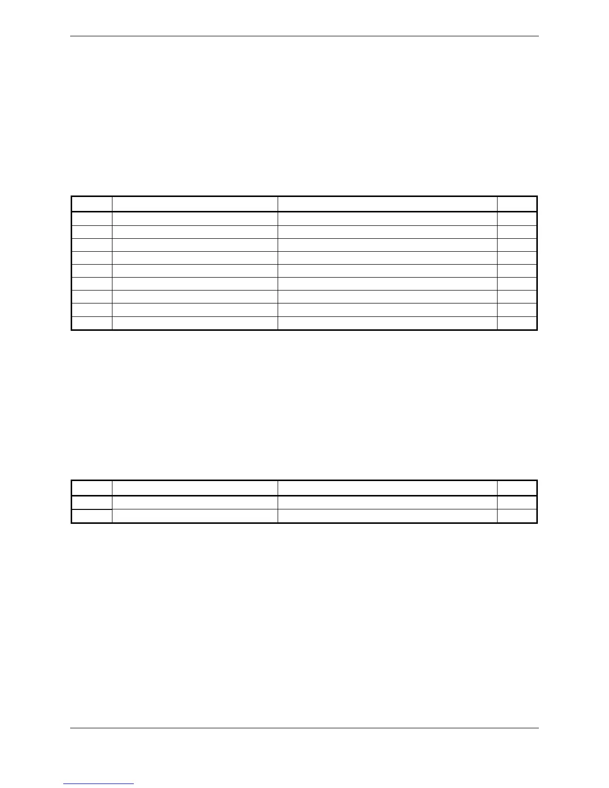
Table 4-3. Aircraft Power Pin Assignments, J3472
Pin Pin Name Description I/O
53 AIRCRAFT POWER 1 Unit power In
55 AIRCRAFT POWER 1 Unit power In
30 AIRCRAFT POWER 2 Unit power In
32 AIRCRAFT POWER 2 Unit power In
69 POWER GROUND Aircraft ground --
71 POWER GROUND Aircraft ground --
14 POWER GROUND Aircraft ground --
16 POWER GROUND Aircraft ground --
27 GMA REMOTE POWER OFF ARINC active high signal turns unit off In
Pins 53 and 55 of J3472 are internally connected to form AIRCRAFT POWER 1. Pins 30 and 32 of
J3472 are internally connected to form AIRCRAFT POWER 2. AIRCRAFT POWER 1 and AIRCRAFT
POWER 2 are “diode ORed” to provide power redundancy.
4.3.2 Lighting Bus
The GMA 1347D can be configured to track a 28 Vdc or 14 Vdc lighting bus using these inputs. The
GMA 1347D can also automatically adjust for ambient lighting conditions based on photocell input on
the PFD/MFD by digital means.
Table 4-4. Aircraft Lighting Pin Assignments, J3472
Pin Pin Name Description I/O
51 14 V LIGHTING HI 14V Backlighting input, 0 to 14 Vdc In
52 28 V LIGHTING HI 28V Backlighting input, 0 to 28 Vdc In
 Loading...


