190-01182-02 GTR 225/GNC 255 TSO Installation Manual
Rev. F Page 6-17
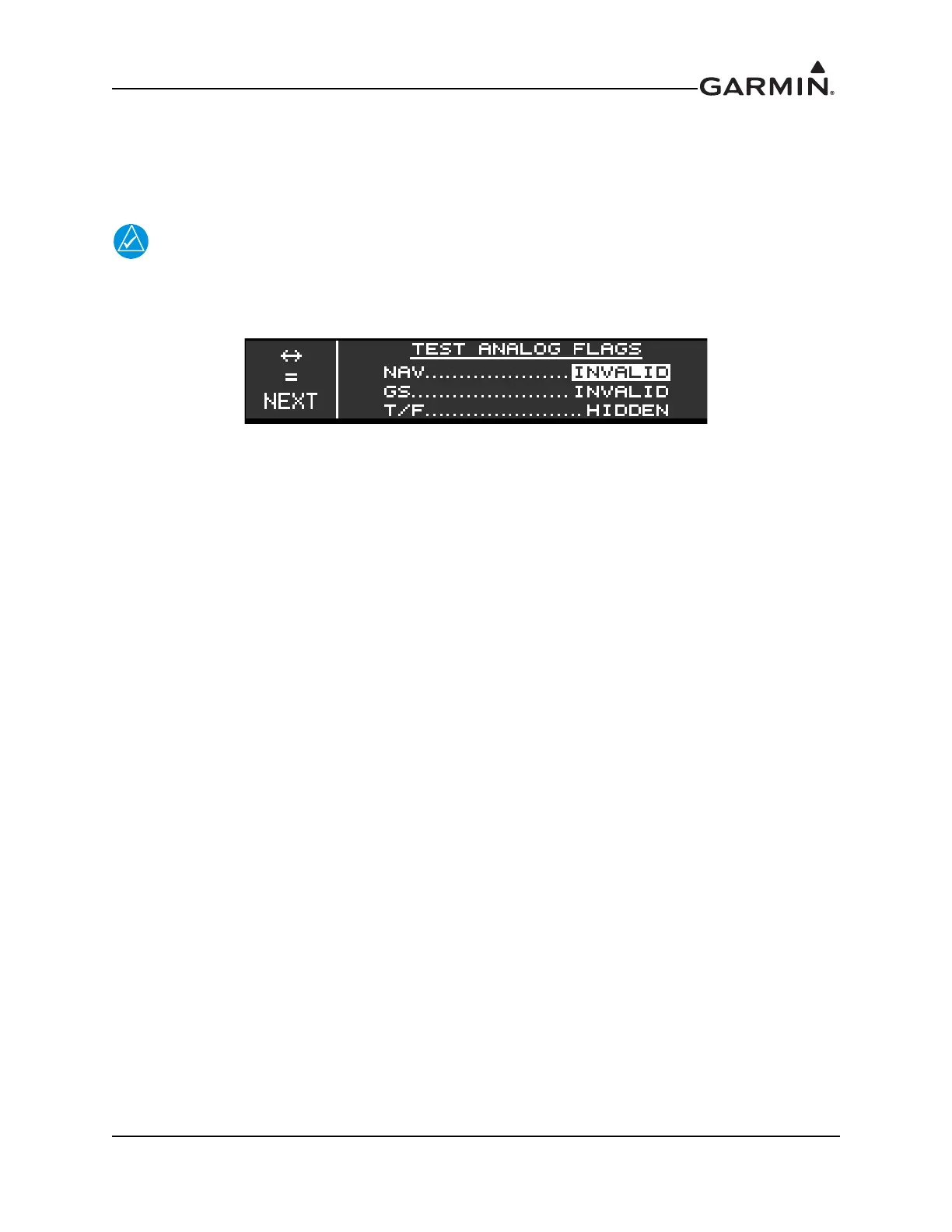
6.5.2 Test Analog Flags (GNC Only)
The TEST ANALOG FLAGS sends an active signal for testing the interface with connected devices. The
test includes NAV (NAV), GS (Glideslope), and T/F (To/From). The TEST ANALOG FLAGS page can
be found in the NAV group (figure 6-1).
Some CDIs/HSIs require that the ILS ENERGIZE discrete be active for flags check and
CDI/VDI check to function properly.
Figure 6-25 Test Analog Flags Page
1. Select the TEST ANALOG FLAGS page.
2. Press ENT.
3. Turn the inner knob to set the NAV flag as VALID or INVALID.
4. Verify the applicable flag is displayed on connected indicator.
5. Turn the outer knob to GS.
6. Turn the inner knob to set the GS flag as VALID or INVALID.
7. Verify the applicable flag is displayed on connected indicator.
8. Turn the outer knob to T/F.
9. Turn the inner knob to set the T/F flag as FROM, TO, or HIDDEN.
10. Verify the flags on the connected indicator function as configured.

 Loading...


