CHAPTER 1: COMMUNICATIONS GUIDE MODBUS FUNCTIONS
345 TRANSFORMER PROTECTION SYSTEM – COMMUNICATIONS GUIDE 1–177
Performing Commands Using Function Code 10H
Commands can be performed using function code 16 as well as function code 5. When
using FUNCTION CODE 16, the Command Function register must be written with a value of
5. The Command Operation register must be written with a valid command operation
number. The Command Data registers must be written with valid data; this is dependent
upon the command operation.
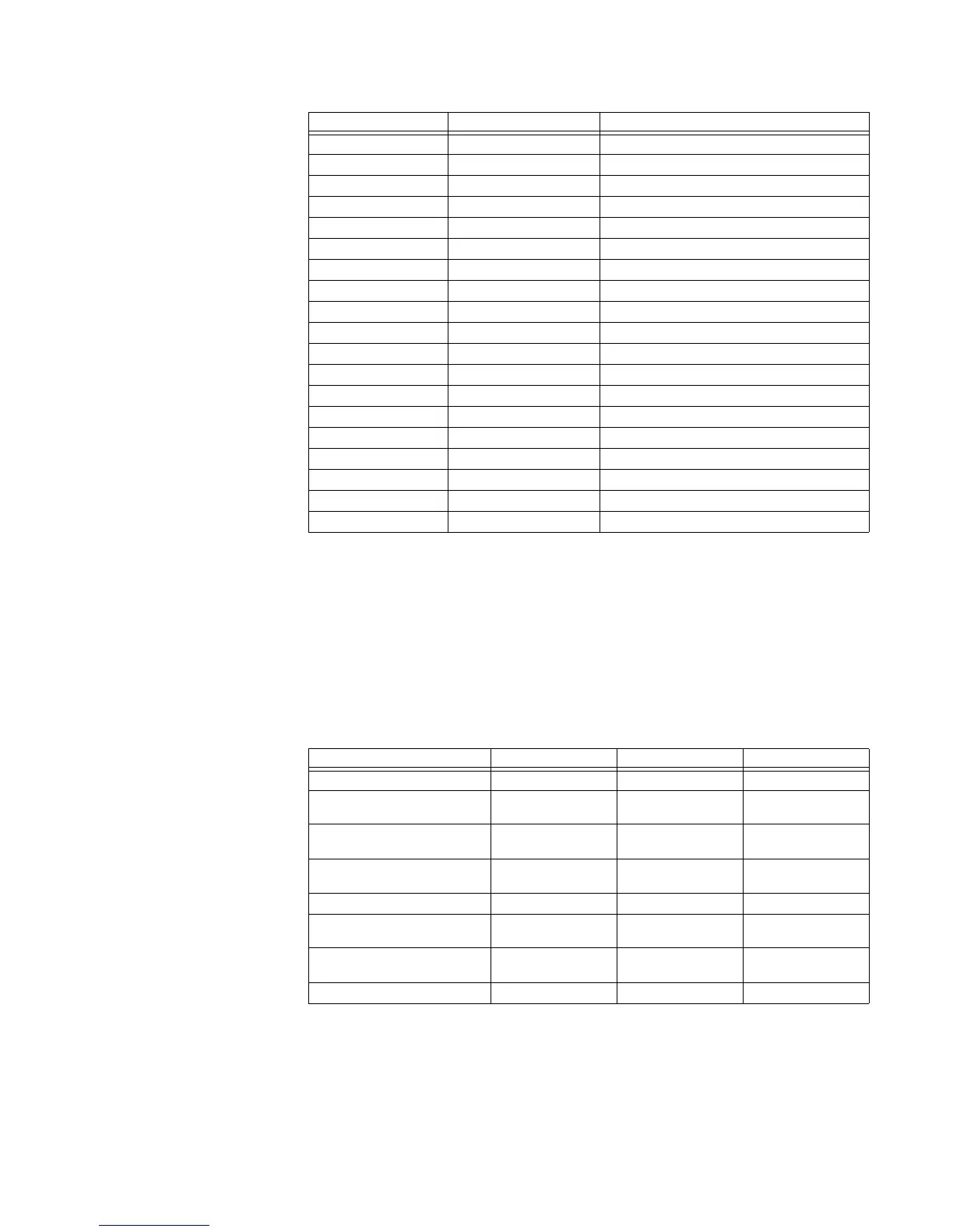
For example, consider a request for slave 17 to perform command operation 1 (RESET): The
master/slave packets have the following format:
Table 41: MASTER/SLAVE PACKET FORMAT FOR PERFORMING COMMANDS
4109 Force Virtual Input 14 State
4110 Force Virtual Input 15 State
4111 Force Virtual Input 16 State
4112 Force Virtual Input 17 State
4113 Force Virtual Input 18 State
4114 Force Virtual Input 19 State
4115 Force Virtual Input 20 State
4116 Force Virtual Input 21 State
4117 Force Virtual Input 22 State
4118 Force Virtual Input 23 State
4119 Force Virtual Input 24 State
4120 Force Virtual Input 25 State
4121 Force Virtual Input 26 State
4122 Force Virtual Input 27 State
4123 Force Virtual Input 28 State
4124 Force Virtual Input 29 State
4125 Force Virtual Input 30 State
4126 Force Virtual Input 31 State
4127 Force Virtual Input 32 State
Modbus Address Hex Address Description
MASTER TRANSMISSION BYTES EXAMPLE DESCRIPTION
SLAVE ADDRESS 1 11 message for slave 17
FUNCTION CODE 1 10 store multiple
setpoints
DATA STARTING ADDRESS 2 00 80 setpoint address 00
80
NUMBER OF SETPOINTS 2 00 02 2 setpoints = 4 bytes
total
BYTE COUNT 1 04 4 bytes of data
DATA 1 2 00 05 data for address 00
80
DATA 2 2 00 01 data for address 00
81
CRC 2 7E CE CRC error code

 Loading...


