GE Multilin B30 Bus Differential System 3-45
3 HARDWARE 3.3 DIRECT INPUT AND OUTPUT COMMUNICATIONS
3
• Flashing yellow — internal mode while receiving a valid data packet
• Solid red — (switch to) internal timing mode while not receiving a valid data packet
The link/activity LED status is as follows:
• Flashing green — FPGA is receiving a valid data packet
• Solid yellow — FPGA is receiving a "yellow bit" and remains yellow for each "yellow bit"
• Solid red — FPGA is not receiving a valid packet or the packet received is invalid
3.3.9 C37.94SM INTERFACE
The UR-series C37.94SM communication modules (2A and 2B) are designed to interface with modified IEEE C37.94 com-
pliant digital multiplexers or IEEE C37.94 compliant interface converters that have been converted from 820 nm multi-mode
fiber optics to 1300 nm ELED single-mode fiber optics. The IEEE C37.94 standard defines a point-to-point optical link for
synchronous data between a multiplexer and a teleprotection device. This data is typically 64 kbps, but the standard pro-
vides for speeds up to 64n kbps, where n = 1, 2,…, 12. The UR-series C37.94SM communication module is 64 kbps only
with n fixed at 1. The frame is a valid International Telecommunications Union (ITU-T) recommended G.704 pattern from
the standpoint of framing and data rate. The frame is 256 bits and is repeated at a frame rate of 8000 Hz, with a resultant bit
rate of 2048 kbps.
The specifications for the module are as follows:
• Emulated IEEE standard: emulates C37.94 for 1 × 64 kbps optical fiber interface (modules set to n = 1 or 64 kbps)
• Fiber optic cable type: 9/125 μm core diameter optical fiber
• Fiber optic mode: single-mode, ELED compatible with HP HFBR-1315T transmitter and HP HFBR-2316T receiver
• Fiber optic cable length: up to 11.4 km
• Fiber optic connector: type ST
• Wavelength: 1300 ±40 nm
• Connection: as per all fiber optic connections, a Tx-to-Rx connection is required
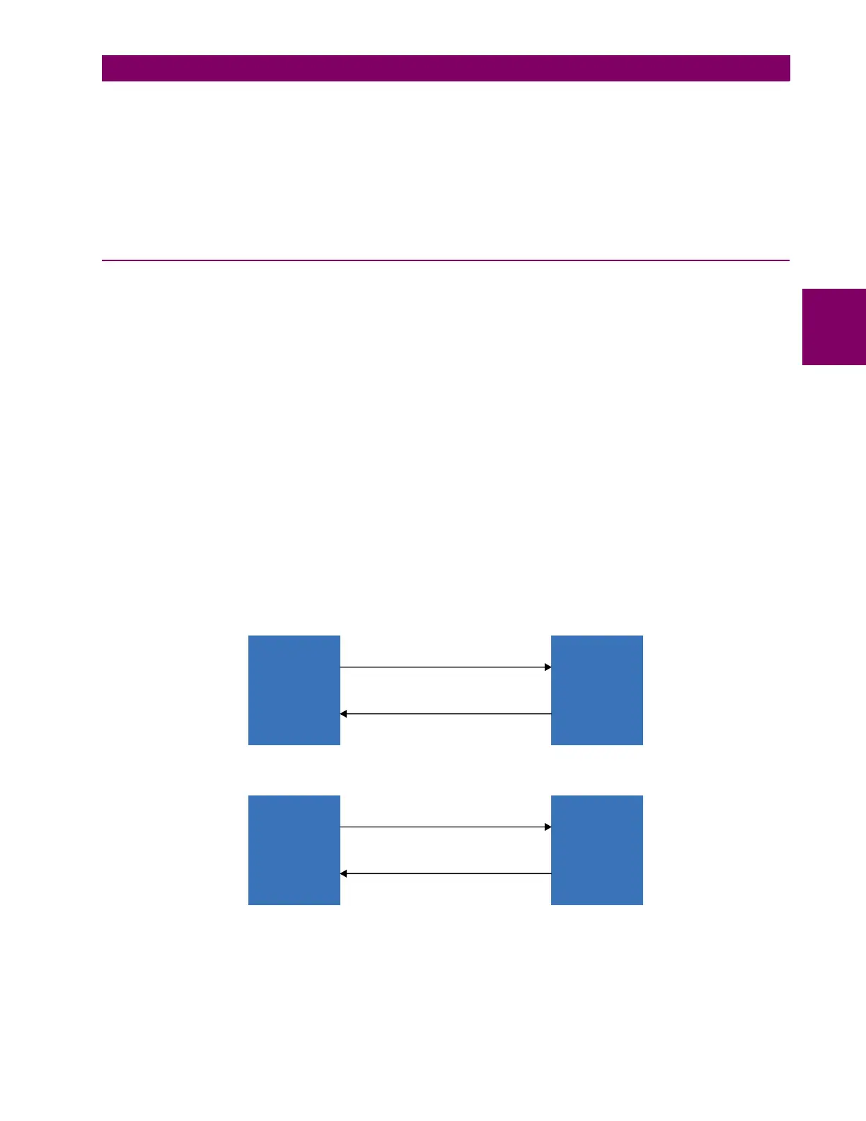
The UR-series C37.94SM communication module can be connected directly to any compliant digital multiplexer that sup-
ports C37.94SM as shown below.
It can also can be connected directly to any other UR-series relay with a C37.94SM module as shown below.
In 2008, GE Grid Solutions released revised modules 2A and 2B for C37.94SM communication to enable multi-ended fault
location functionality with firmware 5.60 release and higher. All modules 2A and 2B shipped since the change support this
feature and are fully backward compatible with firmware releases below 5.60. For customers using firmware release 5.60
UR-series
device
C37.94SM
fiber interface
up to 10 km
842757A2.CDR
Digital
multiplexer
C97.94SM
UR-series
device with
C37.94SM
module
C37.94SM
fiber interface
up to 10 km
UR-series
device with
C37.94SM
module
842758A2.CDR