GE Multilin B30 Bus Differential System 6-11
6 ACTUAL VALUES 6.3 METERING
6
6.3METERING 6.3.1 PARALLEL REDUNDANCY PROTOCOL (PRP)
The Parallel Redundancy Protocol (PRP) defines a redundancy protocol for high availability in substation automation net-
works.
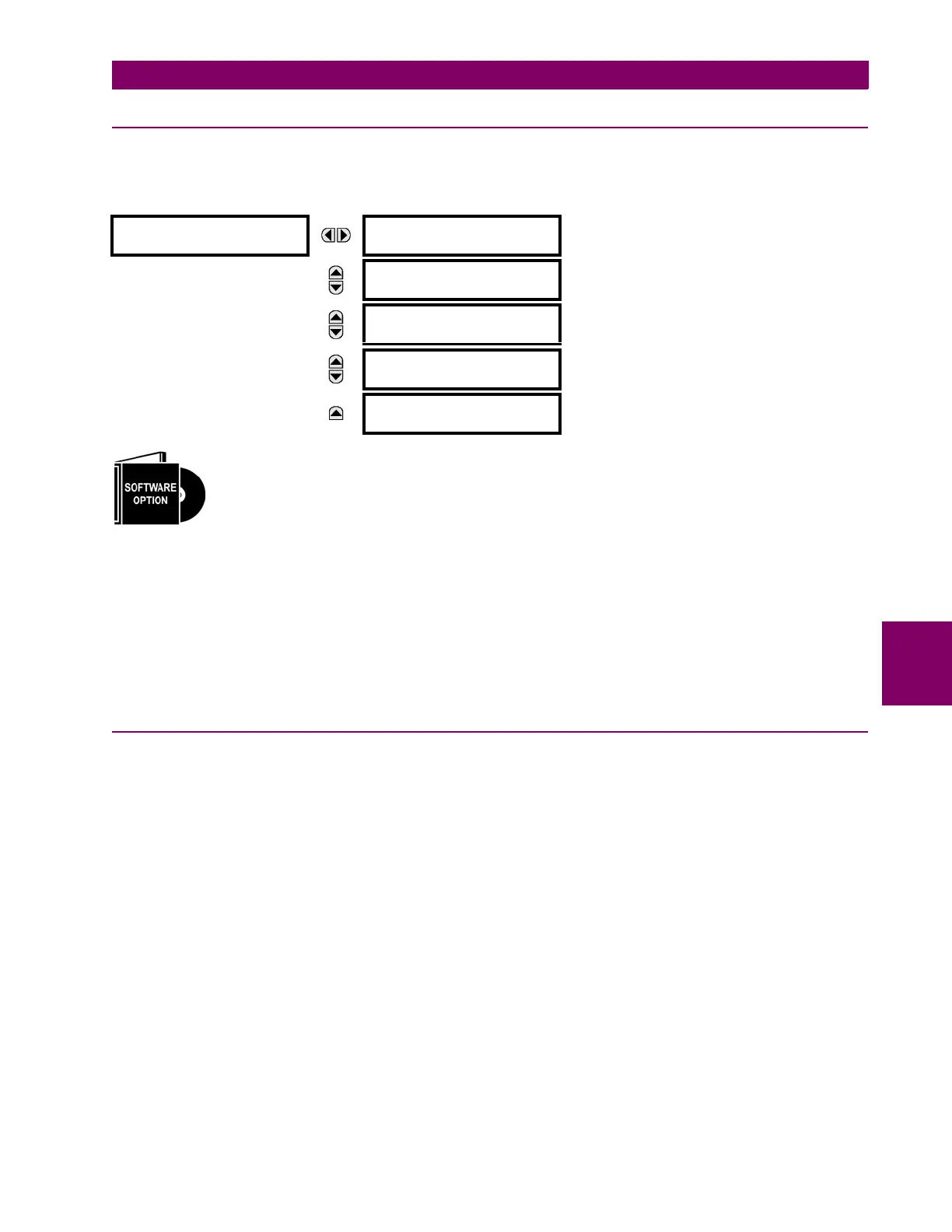
PATH: ACTUAL VALUES STATUS PRP
The B30 Bus Differential System is provided with optional PRP capability. This feature is specified as a
software option at the time of ordering. See the Order Codes section in chapter 2 for details.
TOTAL RECEIVED PORT A is a counter for total messages received (either from DANPs or from SANs) on Port A.
TOTAL RECEIVED PORT B is a counter for total messages received (either from DANPs or from SANs) on Port B.
TOTAL ERRORS is a counter for total messages received with an error (bad port code, frame length too short).
MISMATCHES PORT A is a counter for total messages received with an error on Port A (PRP frame, but port received through
and LAN ID in the frame do not match).
MISMATCHES PORT B is a counter for total messages received with an error on Port B (PRP frame, but port received through
and LAN ID in the frame do not match).
6.3.2 METERING CONVENTIONS
a) UR CONVENTION FOR MEASURING PHASE ANGLES
All phasors calculated by UR-series relays and used for protection, control and metering functions are rotating phasors that
maintain the correct phase angle relationships with each other at all times.
For display and oscillography purposes, all phasor angles in a given relay are referred to an AC input channel pre-selected
by the
SETTINGS SYSTEM SETUP POWER SYSTEM FREQUENCY AND PHASE REFERENCE setting. This setting
defines a particular AC signal source to be used as the reference.
The relay will first determine if any “Phase VT” bank is indicated in the source. If it is, voltage channel VA of that bank is
used as the angle reference. Otherwise, the relay determines if any “Aux VT” bank is indicated; if it is, the auxiliary voltage
channel of that bank is used as the angle reference. If neither of the two conditions is satisfied, then two more steps of this
hierarchical procedure to determine the reference signal include “Phase CT” bank and “Ground CT” bank.
If the AC signal pre-selected by the relay upon configuration is not measurable, the phase angles are not referenced. The
phase angles are assigned as positive in the leading direction, and are presented as negative in the lagging direction, to
more closely align with power system metering conventions. This is illustrated below.
PRP
Total Rx Port A:
Range: 0 to 4G, blank if PRP disabled
MESSAGE
Total Rx Port B:
Range: 0 to 4G, blank if PRP disabled
MESSAGE
Total Errors:
Range: 0 to 4G, blank if PRP disabled
MESSAGE
Mismatches Port A:
Range: 0 to 4G, blank if PRP disabled
MESSAGE
Mismatches Port B:
Range: 0 to 4G, blank if PRP disabled
 Loading...


