5-94 B30 Bus Differential System GE Multilin
5.2 PRODUCT SETUP 5 SETTINGS
5
5.2.16 TELEPROTECTION
PATH: SETTINGS PRODUCT SETUP TELEPROTECTION
This option is available when an INTER-RELAY COMMUNICATIONS card is specified at the time of order-
ing. With the option, direct inputs/outputs display by default. When you enable the teleprotection feature,
direct I/O is not visible.
Digital teleprotection functionality is designed to transfer protection commands between two or three relays in a secure,
fast, dependable, and deterministic fashion. Possible applications are permissive or blocking pilot schemes and direct
transfer trip (DTT). Teleprotection can be applied over any analog or digital channels and any communications media, such
as direct fiber, copper wires, optical networks, or microwave radio links. A mixture of communication media is possible.
Once teleprotection is enabled and the teleprotection input/outputs are configured, data packets are transmitted continu-
ously every 1/4 cycle (3/8 cycle if using C37.94 modules) from peer-to-peer. Security of communication channel data is
achieved by using CRC-32 on the data packet.
Teleprotection inputs/outputs and direct inputs/outputs are mutually exclusive – as such, they cannot be used
simultaneously. Once teleprotection inputs and outputs are enabled, direct inputs and outputs are blocked, and vice
versa.
• NUMBER OF TERMINALS: Specifies whether the teleprotection system operates between two peers or three peers.
• NUMBER OF CHANNELS: Specifies how many channels are used. If the
NUMBER OF TERMINALS is “3” (three-terminal
system), set the
NUMBER OF CHANNELS to “2”. For a two-terminal system, the NUMBER OF CHANNELS can set to “1” or
“2” (redundant channels).
• LOCAL RELAY ID NUMBER, TERMINAL 1 RELAY ID NUMBER, and TERMINAL 2 RELAY ID NUMBER: In installa-
tions that use multiplexers or modems, it is desirable to ensure that the data used by the relays protecting a given line
is from the correct relays. The teleprotection function performs this check by reading the message ID sent by transmit-
ting relays and comparing it to the programmed ID in the receiving relay. This check is also used to block inputs if inad-
vertently set to loopback mode or data is being received from a wrong relay by checking the ID on a received channel.
If an incorrect ID is found on a channel during normal operation, the
TELEPROT CH1 ID FAIL or TELEPROT CH2 ID FAIL
FlexLogic operand is set, driving the event with the same name and blocking the teleprotection inputs. For commis-
sioning purposes, the result of channel identification is also shown in the
STATUS CHANNEL TESTS VALIDITY OF
CHANNEL CONFIGURATION actual value. The default value of “0” for the LOCAL RELAY ID NUMBER indicates that relay ID
is not to be checked. On two- terminals two-channel systems, the same
LOCAL RELAY ID NUMBER is transmitted over
both channels; as such, only the
TERMINAL 1 ID NUMBER has to be programmed on the receiving end.
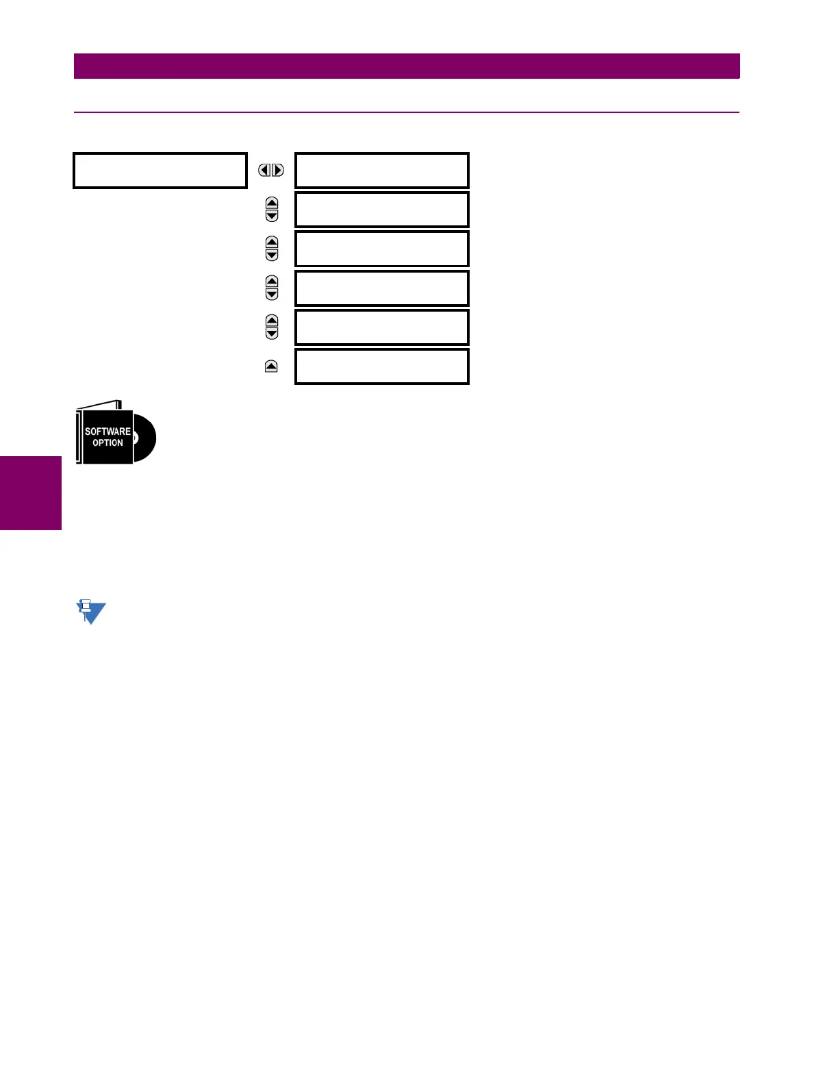
TELEPROTECTION
TELEPROTECTION
FUNCTION: Disabled
Range: Disabled, Enabled
MESSAGE
NUMBER OF TERMINALS:
2
Range: 2, 3
MESSAGE
NUMBER OF COMM
CHANNELS: 1
Range: 1, 2
MESSAGE
LOCAL RELAY ID
NUMBER: 0
Range: 0 to 255 in steps of 1
MESSAGE
TERMINAL 1 RELAY ID
NUMBER: 0
Range: 0 to 255 in steps of 1
MESSAGE
TERMINAL 2 RELAY ID
NUMBER: 0
Range: 0 to 255 in steps of 1
 Loading...


