4-22 C30 Controller System GE Multilin
4.3 FACEPLATE INTERFACE 4 HUMAN INTERFACES
4
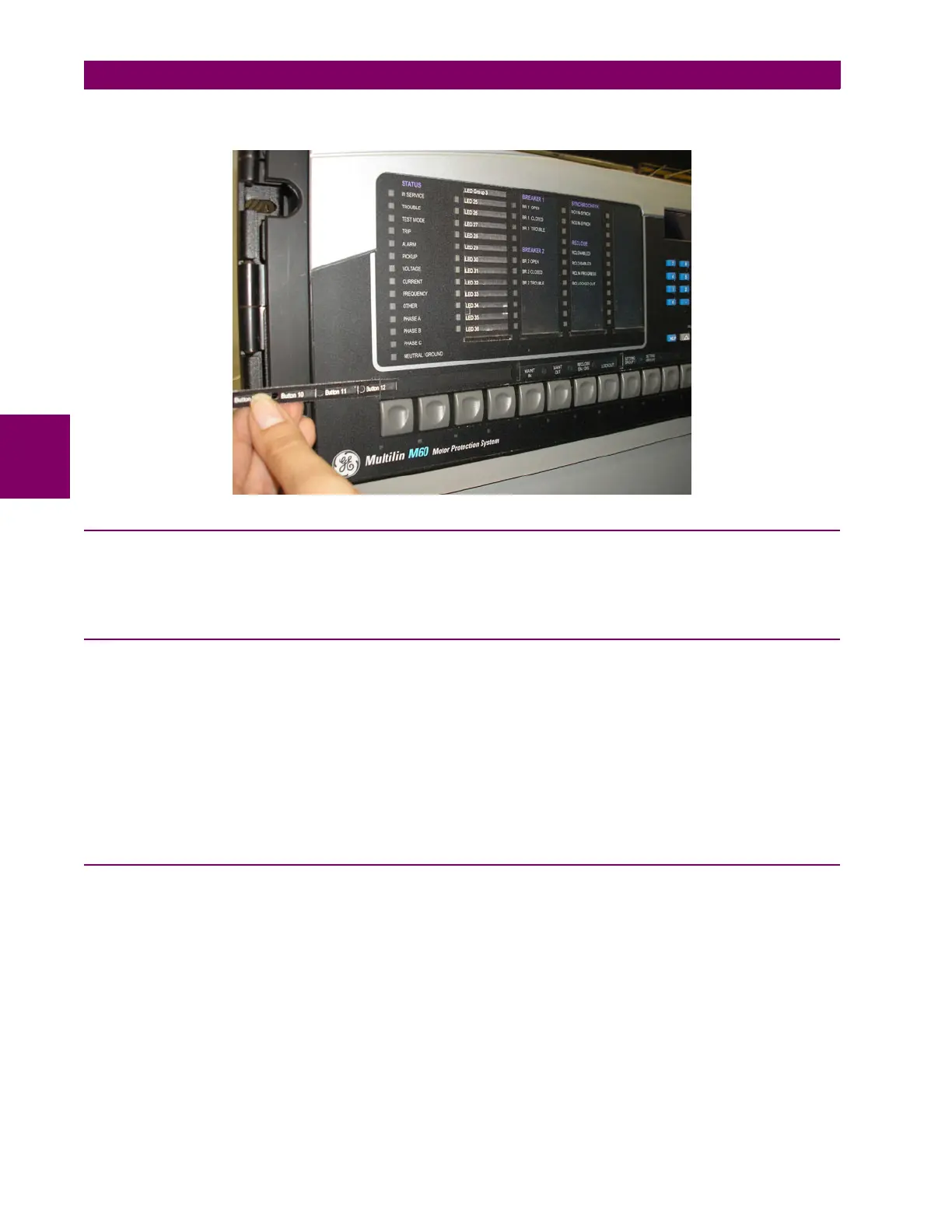
4. Slide the new user-programmable pushbutton label inside the pocket until the text is properly aligned with the buttons,
as shown below.
4.3.4 DISPLAY
All messages are displayed on a backlit liquid crystal display (LCD) to make them visible under poor lighting conditions.
While the keypad and display are not actively being used, the display defaults to user-defined messages. Any high-priority
event-driven message automatically overrides the default message and appears on the display.
4.3.5 KEYPAD
Display messages are organized into pages under the following headings: actual values, settings, commands, and targets.
The MENU key navigates through these pages. Each heading page is divided further into logical subgroups.
The MESSAGE keys navigate through the subgroups. The VALUE keys increment or decrement numerical setting values
when in programming mode. These keys also scroll through alphanumeric values in the text edit mode. Alternatively, val-
ues can be entered with the numeric keypad.
The decimal key initiates and advances to the next character in text edit mode or enters a decimal point.
The HELP key can be pressed at any time for context-sensitive help messages.
The ENTER key stores altered setting values.
4.3.6 BREAKER CONTROL
a) INTRODUCTION
The C30 can interface with associated circuit breakers. In many cases the application monitors the state of the breaker, that
can be presented on faceplate LEDs, along with a breaker trouble indication. Breaker operations can be manually initiated
from faceplate keypad or automatically initiated from a FlexLogic operand. A setting is provided to assign names to each
breaker; this user-assigned name is used for the display of related flash messages. These features are provided for two
breakers; the user can use only those portions of the design relevant to a single breaker, which must be breaker 1.
For the following discussion it is assumed the SETTINGS SYSTEM SETUP BREAKERS BREAKER 1(2) BREAKER
FUNCTION setting is "Enabled" for each breaker.

 Loading...