GE Multilin C30 Controller System 5-65
5 SETTINGS 5.2 PRODUCT SETUP
5
PUSHBUTTON 1 FUNCTION: “Self-reset”
PUSHBTN 1 DROP-OUT TIME: “0.10 s”
Configure the LED test to recognize user-programmable pushbutton 1 by making the following entries in the SETTINGS
PRODUCT SETUP USER-PROGRAMMABLE LEDS LED TEST menu:
LED TEST FUNCTION: “Enabled”
LED TEST CONTROL: “PUSHBUTTON 1 ON”
The test will be initiated when the user-programmable pushbutton 1 is pressed. The pushbutton should remain pressed for
as long as the LEDs are being visually inspected. When finished, the pushbutton should be released. The relay will then
automatically start stage 2. At this point forward, test may be aborted by pressing the pushbutton.
APPLICATION EXAMPLE 2:
Assume one needs to check if any LEDs are “burned” as well as exercise one LED at a time to check for other failures. This
is to be performed via user-programmable pushbutton 1.
After applying the settings in application example 1, hold down the pushbutton as long as necessary to test all LEDs. Next,
release the pushbutton to automatically start stage 2. Once stage 2 has started, the pushbutton can be released. When
stage 2 is completed, stage 3 will automatically start. The test may be aborted at any time by pressing the pushbutton.
c) TRIP AND ALARM LEDS
PATH: SETTINGS PRODUCT SETUP USER-PROGRAMMABLE LEDS TRIP & ALARM LEDS
The trip and alarm LEDs are in the first LED column (enhanced faceplate) and on LED panel 1 (standard faceplate). Each
indicator can be programmed to become illuminated when the selected FlexLogic operand is in the logic 1 state.
d) USER-PROGRAMMABLE LED 1(48)
PATH: SETTINGS PRODUCT SETUP USER-PROGRAMMABLE LEDS USER-PROGRAMMABLE LED 1(48)
There are 48 amber LEDs across the relay faceplate LED panels. Each of these indicators can be programmed to illumi-
nate when the selected FlexLogic operand is in the logic 1 state.
For the standard faceplate, the LEDs are located as follows.
• LED Panel 2: user-programmable LEDs 1 through 24
• LED Panel 3: user programmable LEDs 25 through 48
For the enhanced faceplate, the LEDs are located as follows.
• LED column 2: user-programmable LEDs 1 through 12
• LED column 3: user-programmable LEDs 13 through 24
• LED column 4: user-programmable LEDs 25 through 36
• LED column 5: user-programmable LEDs 37 through 48
Refer to the LED indicators section in chapter 4 for additional information on the location of these indexed LEDs.
The user-programmable LED settings select the FlexLogic operands that control the LEDs. If the
LED 1 TYPE setting is “Self-
Reset” (the default setting), the LED illumination will track the state of the selected LED operand. If the
LED 1 TYPE setting is
“Latched”, the LED, once lit, remains so until reset by the faceplate RESET button, from a remote device via a communica-
tions channel, or from any programmed operand, even if the LED operand state de-asserts.
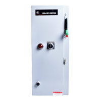
TRIP & ALARM LEDS
TRIP LED INPUT:
Off
Range: FlexLogic operand
MESSAGE
ALARM LED INPUT:
Off
Range: FlexLogic operand
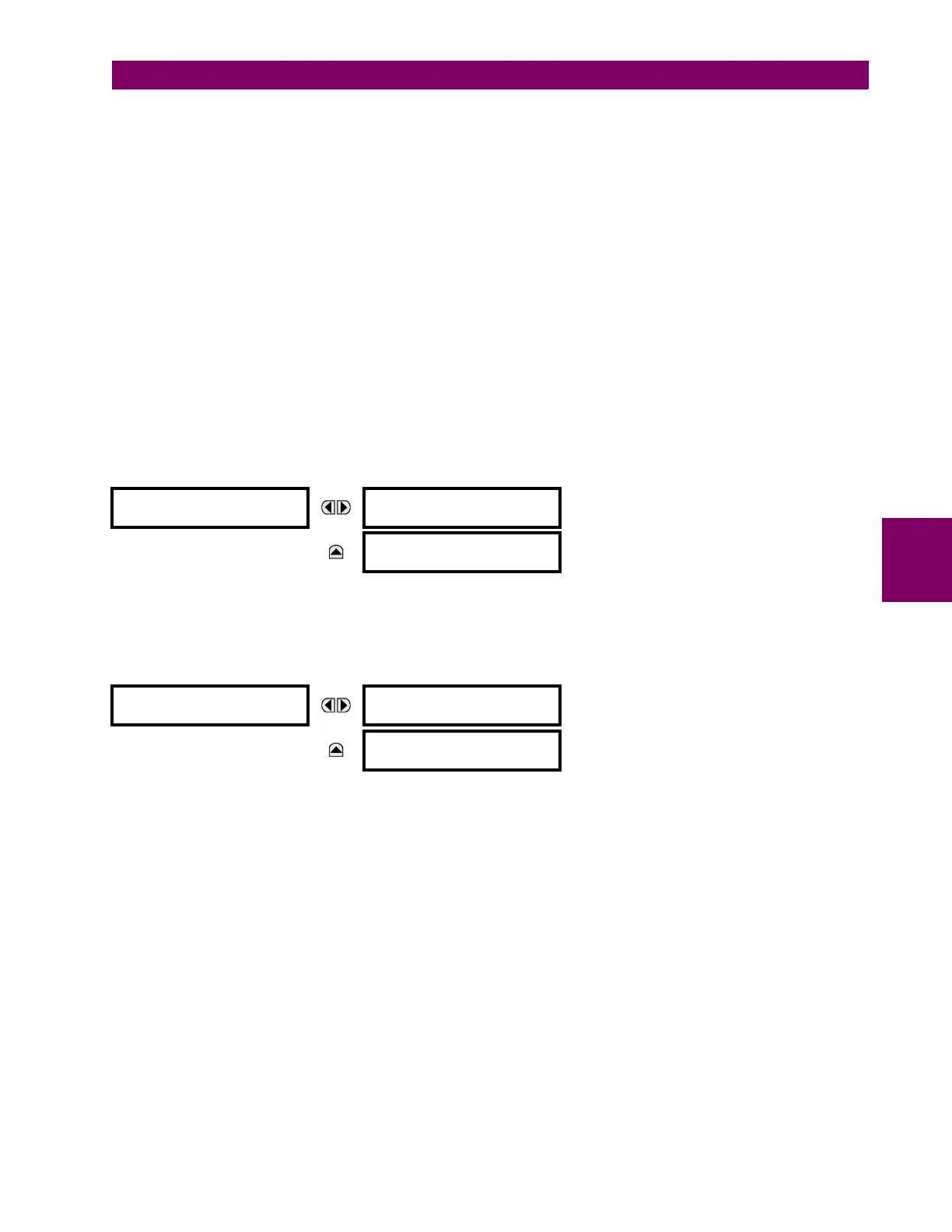
USER-PROGRAMMABLE
LED 1
LED 1 OPERAND:
Off
Range: FlexLogic operand
MESSAGE
LED 1 TYPE:
Self-Reset
Range: Self-Reset, Latched

 Loading...