GE Multilin C30 Controller System 5-69
5 SETTINGS 5.2 PRODUCT SETUP
5
The optional user-programmable pushbuttons (specified in the order code) provide an easy and error-free method of enter-
ing digital state (on, off) information. The number of available pushbuttons is dependent on the faceplate module ordered
with the relay.
• Type P faceplate: standard horizontal faceplate with 12 user-programmable pushbuttons.
• Type Q faceplate: enhanced horizontal faceplate with 16 user-programmable pushbuttons.
The digital state can be entered locally (by directly pressing the front panel pushbutton) or remotely (via FlexLogic oper-
ands) into FlexLogic equations, protection elements, and control elements. Typical applications include breaker control,
autorecloser blocking, and setting groups changes. The user-programmable pushbuttons are under the control level of
password protection.
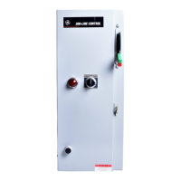
The user-configurable pushbuttons for the enhanced faceplate are shown below.
Figure 5–12: USER-PROGRAMMABLE PUSHBUTTONS (ENHANCED FACEPLATE)
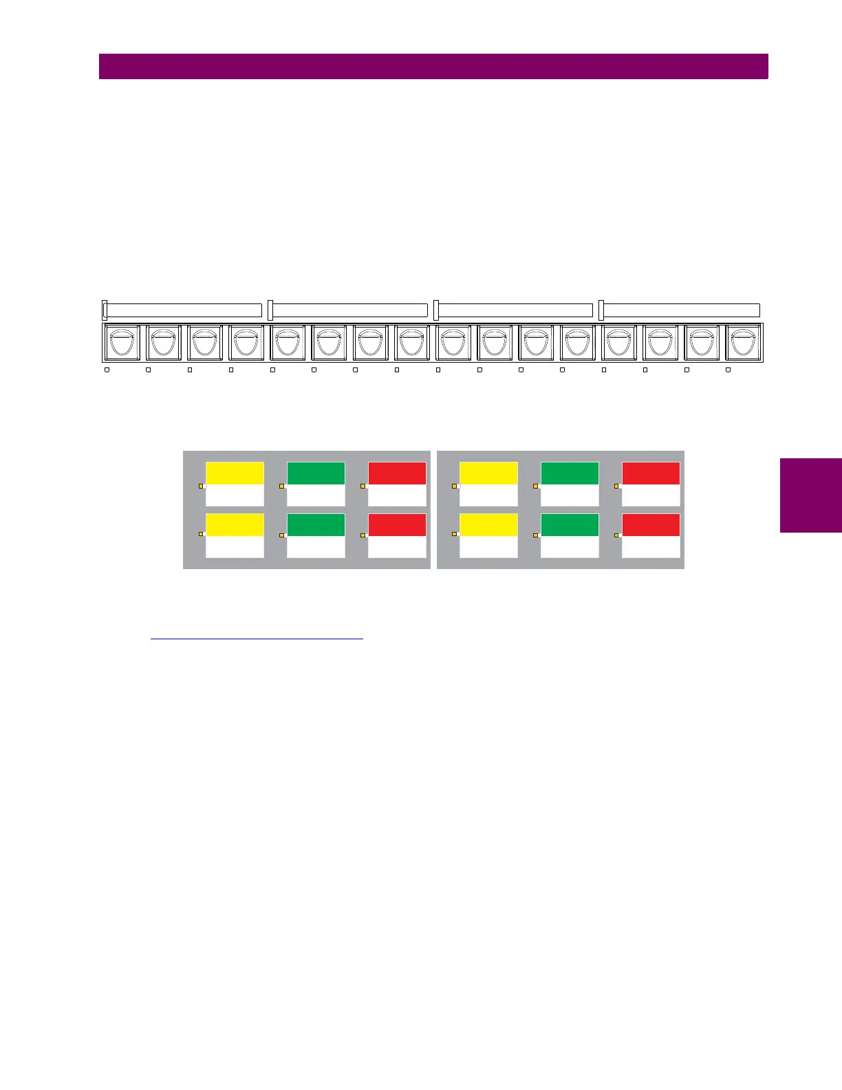
The user-configurable pushbuttons for the standard faceplate are shown below.
Figure 5–13: USER-PROGRAMMABLE PUSHBUTTONS (STANDARD FACEPLATE)
Both the standard and enhanced faceplate pushbuttons can be custom labeled with a factory-provided template, available
online at http://www.gedigitalenergy.com/multilin
. The EnerVista UR Setup software can also be used to create labels for
the enhanced faceplate.
Each pushbutton asserts its own “On” and “Off” FlexLogic operands (for example, PUSHBUTTON 1 ON and PUSHBUTTON 1
OFF
). These operands are available for each pushbutton and are used to program specific actions. If any pushbutton is
active, the ANY PB ON operand will be asserted.
Each pushbutton has an associated LED indicator. By default, this indicator displays the present status of the correspond-
ing pushbutton (on or off). However, each LED indicator can be assigned to any FlexLogic operand through the PUSHBTN 1
LED CTL
setting.
The pushbuttons can be automatically controlled by activating the operands assigned to the
PUSHBTN 1 SET (for latched and
self-reset mode) and
PUSHBTN 1 RESET (for latched mode only) settings. The pushbutton reset status is declared when the
PUSHBUTTON 1 OFF operand is asserted. The activation and deactivation of user-programmable pushbuttons is dependent
on whether latched or self-reset mode is programmed.
• Latched mode: In latched mode, a pushbutton can be set (activated) by asserting the operand assigned to the PUSH-
BTN 1 SET
setting or by directly pressing the associated front panel pushbutton. The pushbutton maintains the set state
until deactivated by the reset command or after a user-specified time delay. The state of each pushbutton is stored in
non-volatile memory and maintained through a loss of control power.
The pushbutton is reset (deactivated) in latched mode by asserting the operand assigned to the PUSHBTN 1 RESET set-
ting or by directly pressing the associated active front panel pushbutton.
842814A1.CDR
USER
LABEL 1
USER
LABEL 2
USER
LABEL 3
USER
LABEL 4
USER
LABEL 5
USER
LABEL 6
USER
LABEL 7
USER
LABEL 8
USER
LABEL 9
USER
LABEL 10
USER
LABEL 11
USER
LABEL 12
USER
LABEL 13
USER
LABEL 14
USER
LABEL 15
USER
LABEL 16
USER LABEL USER LABEL
USER LABEL
USER LABEL USER LABEL USER LABEL
7911
81012
USER LABEL
135
246
USER LABEL
USER LABEL
USER LABEL USER LABEL USER LABEL
842779A1.cdr

 Loading...