EasyManua.ls Logo

GE C30 User Manual

GE C30
480 pages
To Next Page IconTo Next Page
To Previous Page IconTo Previous Page
Page #455 background imageLoading...
Page #455 background image
GE Multilin C30 Controller System E-5
APPENDIX E E.1 DEVICE PROFILE DOCUMENT
E
20
cont’d
2 16-Bit Binary Counter 1 (read)
7 (freeze)
8 (freeze noack)
9 (freeze clear)
10 (frz. cl. noack)
22 (assign class)
00, 01 (start-stop)
06 (no range, or all)
07, 08 (limited quantity)
17, 28 (index)
129 (response) 00, 01 (start-stop)
17, 28 (index)
(see Note 2)
5 32-Bit Binary Counter without Flag 1
(read)
7 (freeze)
8 (freeze noack)
9 (freeze clear)
10 (frz. cl. noack)
22 (assign class)
00, 01 (start-stop)
06 (no range, or all)
07, 08 (limited quantity)
17, 28 (index)
129 (response) 00, 01 (start-stop)
17, 28 (index)
(see Note 2)
6 16-Bit Binary Counter without Flag 1 (read)
7 (freeze)
8 (freeze noack)
9 (freeze clear)
10 (frz. cl. noack)
22 (assign class)
00, 01 (start-stop)
06 (no range, or all)
07, 08 (limited quantity)
17, 28 (index)
129 (response) 00, 01 (start-stop)
17, 28 (index)
(see Note 2)
21 0 Frozen Counter
(Variation 0 is used to request default
variation)
1 (read)
22 (assign class)
00, 01 (start-stop)
06 (no range, or all)
07, 08 (limited quantity)
17, 28 (index)
1 32-Bit Frozen Counter 1 (read)
22 (assign class)
00, 01 (start-stop)
06 (no range, or all)
07, 08 (limited quantity)
17, 28 (index)
129 (response) 00, 01 (start-stop)
17, 28 (index)
(see Note 2)
2 16-Bit Frozen Counter 1 (read)
22 (assign class)
00, 01 (start-stop)
06 (no range, or all)
07, 08 (limited quantity)
17, 28 (index)
129 (response) 00, 01 (start-stop)
17, 28 (index)
(see Note 2)
9 32-Bit Frozen Counter without Flag 1 (read)
22 (assign class)
00, 01 (start-stop)
06 (no range, or all)
07, 08 (limited quantity)
17, 28 (index)
129 (response) 00, 01 (start-stop)
17, 28 (index)
(see Note 2)
10 16-Bit Frozen Counter without Flag 1 (read)
22 (assign class)
00, 01 (start-stop)
06 (no range, or all)
07, 08 (limited quantity)
17, 28 (index)
129 (response) 00, 01 (start-stop)
17, 28 (index)
(see Note 2)
22 0 Counter Change Event (Variation 0 is used
to request default variation)
1 (read) 06 (no range, or all)
07, 08 (limited quantity)
1 32-Bit Counter Change Event 1 (read) 06 (no range, or all)
07, 08 (limited quantity)
129 (response)
130 (unsol. resp.)
17, 28 (index)
2 16-Bit Counter Change Event 1 (read) 06 (no range, or all)
07, 08 (limited quantity)
129 (response)
130 (unsol. resp.)
17, 28 (index)
5 32-Bit Counter Change Event with Time 1 (read) 06 (no range, or all)
07, 08 (limited quantity)
129 (response)
130 (unsol. resp.)
17, 28 (index)
6 16-Bit Counter Change Event with Time 1 (read) 06 (no range, or all)
07, 08 (limited quantity)
129 (response)
130 (unsol. resp.)
17, 28 (index)
23 0 Frozen Counter Event (Variation 0 is used
to request default variation)
1 (read) 06 (no range, or all)
07, 08 (limited quantity)
1 32-Bit Frozen Counter Event 1 (read) 06 (no range, or all)
07, 08 (limited quantity)
129 (response)
130 (unsol. resp.)
17, 28 (index)
2 16-Bit Frozen Counter Event 1 (read) 06 (no range, or all)
07, 08 (limited quantity)
129 (response)
130 (unsol. resp.)
17, 28 (index)
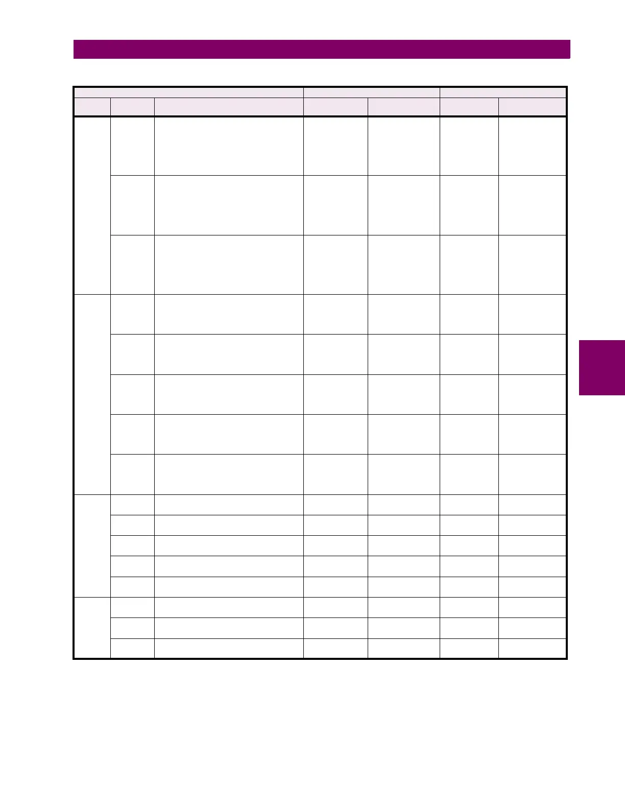
Table E–2: IMPLEMENTATION TABLE (Sheet 2 of 4)
OBJECT REQUEST RESPONSE
OBJECT
NO.
VARIATION
NO.
DESCRIPTION FUNCTION
CODES (DEC)
QUALIFIER
CODES (HEX)
FUNCTION
CODES (DEC)
QUALIFIER
CODES (HEX)
Note 1: A default variation refers to the variation responded when variation 0 is requested and/or in class 0, 1, 2, or 3 scans. The default varia-
tions for object types 1, 2, 20, 21, 22, 23, 30, and 32 are selected via relay settings. Refer to the Communications section in Chapter 5
for details. This optimizes the class 0 poll data size.
Note 2: For static (non-change-event) objects, qualifiers 17 or 28 are only responded when a request is sent with qualifiers 17 or 28, respec-
tively. Otherwise, static object requests sent with qualifiers 00, 01, 06, 07, or 08, will be responded with qualifiers 00 or 01 (for change-
event objects, qualifiers 17 or 28 are always responded.)
Note 3: Cold restarts are implemented the same as warm restarts – the C30 is not restarted, but the DNP process is restarted.

Table of Contents

Question and Answer IconNeed help?

Do you have a question about the GE C30 and is the answer not in the manual?

GE C30 Specifications

General IconGeneral
BrandGE
ModelC30
CategoryController
LanguageEnglish

Summary

1. GETTING STARTED

1.1 IMPORTANT PROCEDURES

Covers essential procedures for initial setup, including cautions, warnings, and inspection protocols.

1.2 OVERVIEW

Provides a general introduction to the UR series, its hardware and software architecture, and key concepts.

1.3 ENERVISTA UR SETUP SOFTWARE

Details the requirements, installation, and configuration of the EnerVista UR Setup software.

1.4 UR HARDWARE

Describes the physical aspects of the UR hardware, including mounting, wiring, and the faceplate display.

1.5 USING THE RELAY

Explains how to navigate and operate the relay using the faceplate keypad and menus.

2. PRODUCT DESCRIPTION

2.1 INTRODUCTION

Provides an overview of the C30 Controller System, its features, communication options, and security aspects.

2.2 SPECIFICATIONS

Details the technical specifications of the C30 Controller System, including protection elements, inputs, outputs, and communication protocols.

3. HARDWARE

3.1 DESCRIPTION

Describes the hardware components of the C30 Controller System, including panel cutouts and terminal layouts.

3.2 WIRING

Provides guidance on typical wiring diagrams, dielectric strength, control power, process bus modules, and contact I/O.

4. HUMAN INTERFACES

4.1 ENERVISTA UR SETUP SOFTWARE INTERFACE

Explains the EnerVista UR Setup software's GUI, engaging devices, using settings files, and firmware upgrades.

4.2 EXTENDED ENERVISTA UR SETUP FEATURES

Covers advanced features like settings templates, securing FlexLogic equations, and settings file traceability.

4.3 FACEPLATE INTERFACE

Details the enhanced and standard faceplate layouts, LED indicators, keypad usage, and breaker control.

5. SETTINGS

5.1 OVERVIEW

Provides an overview of the settings menu, including sections for security, system setup, and FlexLogic.

5.2 PRODUCT SETUP

Details various product setup configurations, including security, network, DNP, IEC 61850, and Modbus protocols.

5.3 REMOTE RESOURCES

Explains how to configure remote resources, specifically for use with HardFiber Bricks and process bus modules.

5.4 SYSTEM SETUP

Covers system setup configurations for breakers and disconnect switches, including their logic schemes.

5.5 FLEXLOGIC

Introduces FlexLogic, its rules, evaluation, and provides examples for creating equations and virtual outputs.

5.6 CONTROL ELEMENTS

Describes control elements such as trip buses, selector switches, digital elements, counters, and PID regulators.

5.7 INPUTS AND OUTPUTS

Details configuration for contact inputs, virtual inputs, outputs, remote devices, and direct I/O.

5.8 TRANSDUCER INPUTS AND OUTPUTS

Explains the configuration of DCmA inputs, RTD inputs, and DCmA outputs for transducer interfacing.

5.9 TESTING

Covers test modes, forcing contact inputs and outputs, and provides application examples for testing procedures.

6. ACTUAL VALUES

6.1 OVERVIEW

Provides an overview of the Actual Values menu, listing categories such as Status, Metering, Records, and Product Info.

6.2 STATUS

Displays the current status of various inputs, outputs, remote devices, Ethernet, and communication links.

6.3 METERING

Shows actual values for FlexElements, IEC 61850 GOOSE analog values, and transducer inputs/outputs.

6.4 RECORDS

Provides access to event records, oscillography data, and data logger information for analysis.

6.5 PRODUCT INFORMATION

Displays model information, including order codes, serial numbers, and firmware revisions.

7. COMMANDS AND TARGETS

7.1 COMMANDS

Lists relay directives for operations personnel, including commands for virtual inputs, records, date/time, and security.

7.2 TARGETS

Describes how target messages are displayed and prioritized, including major and minor self-test error messages.

8. MAINTENANCE

8.1 MODULES

Provides instructions for safely withdrawing and inserting modules, and replacing the CPU module or faceplate.

8.2 BATTERIES

Details battery replacement procedures, including safety precautions and disposal instructions.

8.3 UNINSTALL AND CLEAR FILES AND DATA

Explains how to decommission the unit, clear files, and manage data security regulations.

8.4 REPAIRS

Outlines the process for returning the device to the factory for repair, including RMA procedures.

8.5 STORAGE

Provides guidelines for storing the unit indoors in a cool, dry place, and maintaining electrolytic capacitors.

8.6 DISPOSAL

Specifies disposal requirements for the unit and its battery, emphasizing recycling and component removal.

APPENDIX C IEC 61850 COMMUNICATIONS

C.1 OVERVIEW

Introduces the IEC 61850 standard, its components, and communication profiles like client/server and peer-to-peer.

C.2 SERVER DATA ORGANIZATION

Explains the object-oriented data structure of IEC 61850, including logical nodes for digital and analog values.

C.3 SERVER FEATURES AND CONFIGURATION

Details features like reporting, file transfer, timestamps, logical device naming, and location settings.

C.4 GENERIC SUBSTATION EVENT SERVICES: GSSE AND GOOSE

Describes GSSE and GOOSE communication services, including their configuration and recommended usage.

C.5 IEC 61850 IMPLEMENTATION VIA ENERVISTA UR SETUP

Guides on creating ICD files, understanding SCD files, and importing configuration using EnerVista UR Setup.

C.6 ACSI CONFORMANCE

Details the ACSI basic conformance statement and models, including services supported by the UR family.

C.7 LOGICAL NODES

Provides a table of IEC 61850 logical nodes supported by the UR-series relays, categorized for system equipment.

APPENDIX D IEC 60870-5-104 COMMUNICATIONS

D.1 IEC 60870-5-104

Covers the interoperability document, network configuration, physical layer, and link layer for IEC 60870-5-104.

D.1.1 INTEROPERABILITY DOCUMENT

Details the system, network, and physical layer configurations required for IEC 60870-5-104 standard compliance.

D.1.2 POINT LIST

Lists the DNP and IEC 60870-5-104 data points, including binary inputs, outputs, and MME points.

APPENDIX E DEVICE PROFILE DOCUMENT

E.1 DEVICE PROFILE DOCUMENT

Provides the DNP V3.00 Device Profile, detailing supported objects, functions, and application layer confirmations.

E.1.1 DNP V3.00 DEVICE PROFILE

Details the DNP V3.00 Device Profile, including supported objects, functions, and communication parameters.

E.1.2 IMPLEMENTATION TABLE

Lists the DNP variations, function codes, and qualifiers supported by the C30 for requests and responses.

E.2 DNP POINT LISTS

Provides lists for DNP binary inputs, binary/control relay outputs, counters, and analog inputs.

E.2.1 BINARY INPUT POINTS

Details the static and change event variations for DNP binary input points, including object numbers and scan rates.

E.2.2 BINARY AND CONTROL RELAY OUTPUT

Lists supported control relay output block fields and provides tables for binary/control outputs.

E.2.3 COUNTERS

Details DNP binary and frozen counters, including static variations and default classes for points.

E.2.4 ANALOG INPUTS

Explains DNP analog input data points, including variations, deadbands, and scale factors.

APPENDIX F RADIUS SERVER

F.1 RADIUS SERVER CONFIGURATION

Provides a step-by-step example for setting up a simple RADIUS server using FreeRADIUS software.

F.1.1 RADIUS SERVER CONFIGURATION

Details the procedure for configuring RADIUS server parameters for UR devices, including IP address and shared secret.

APPENDIX G CHANGE NOTES

G.1 CHANGE NOTES

Lists revision history and major updates for C30 manual revisions Z1, Y3, and Y2.

G.1.1 REVISION HISTORY

Provides a table detailing manual P/N, revision, release date, and ECO for C30 controller system manuals.

G.1.2 CHANGES TO THE C30 MANUAL

Lists major updates made to the C30 manual across different revisions, detailing added, updated, or deleted content.

APPENDIX G WARRANTY

G.3 WARRANTY

Outlines the warranty terms for GE manufactured products, including duration and limitations.

G.3.1 GE MULTILIN WARRANTY

Details the GE Multilin warranty policy, specifying warranty periods based on product shipment dates.

Related product manuals