3-22 C30 Controller System GE Multilin
3.2 WIRING 3 HARDWARE
3
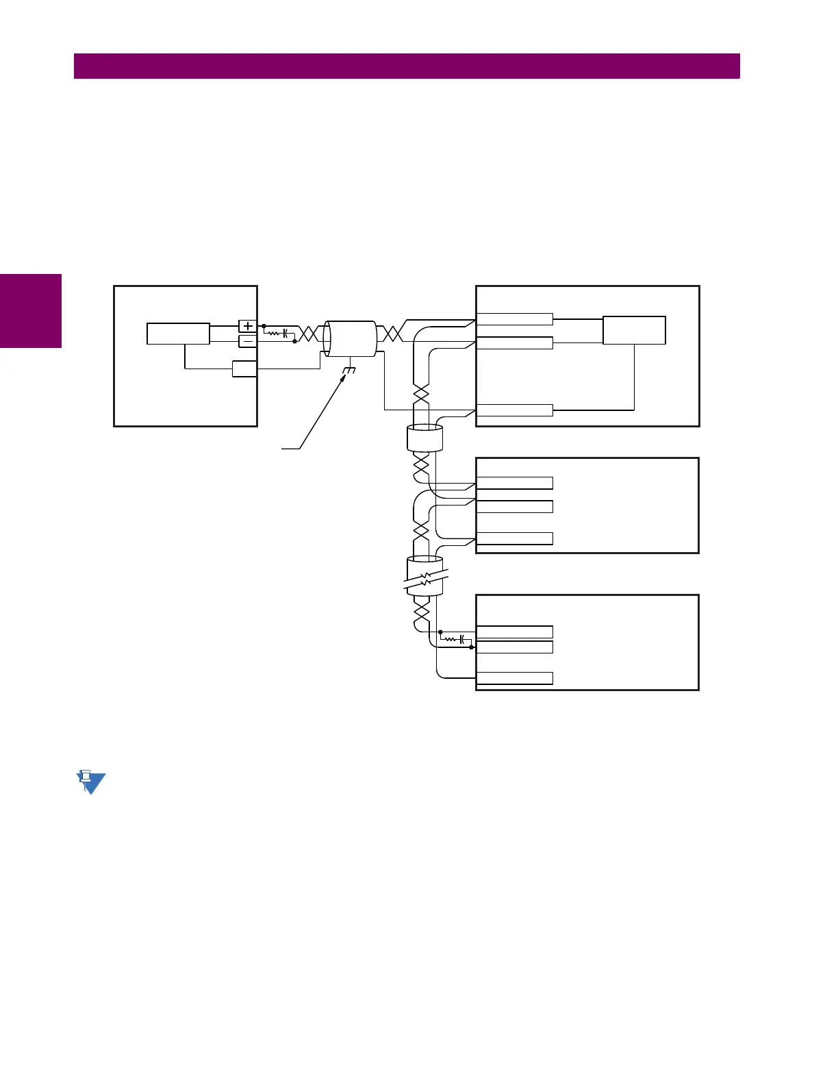
To avoid loop currents, ground the shield at only one point. If other system considerations require the shield to be grounded
at more than one point, install resistors (typically 100 ohms) between the shield and ground at each grounding point. Each
relay needs to be daisy-chained to the next one in the link. A maximum of 32 relays can be connected in this manner with-
out exceeding driver capability. For larger systems, additional serial channels must be added. It is also possible to use com-
mercially available repeaters to have more than 32 relays on a single channel. Avoid star or stub connections entirely.
Lightning strikes and ground surge currents can cause large momentary voltage differences between remote ends of the
communication link. For this reason, surge protection devices are internally provided at both communication ports. An iso-
lated power supply with an optocoupled data interface also acts to reduce noise coupling. To ensure maximum reliability, all
equipment should have similar transient protection devices installed.
Terminate both ends of the RS485 circuit with an impedance as shown below.
Figure 3–22: RS485 SERIAL CONNECTION
c) 10BASE-FL AND 100BASE-FX FIBER OPTIC PORTS
Ensure that the dust covers are installed when the fiber is not in use. Dirty or scratched connectors can lead to high
losses on a fiber link.
The fiber optic communication ports allow for fast and efficient communications between relays at 100 Mbps. Optical fiber
can be connected to the relay supporting a wavelength of 1310 nm in multi-mode.
SCADA / PLC / computer
Optocoupler
Data
UR-series device
Shield
827757AA.CDR
Last device
Z (*)
T
Z (*) Terminating impedance at
T
each end (typically 120 Ω and 1 nF)
Twisted pair
RS485 +
RS485 –
COMP 485COM
Relay
Relay
Ground shield at SCADA / PLC /
computer only or at
UR-series device only
Data
Optocoupler
Up to 32 devices,
maximum 4000 feet
(1200 m)
Z (*)
T
RS485 +
RS485 –
COMP 485COM
RS485 +
RS485 –
COMP 485COM
COM

 Loading...