modifications reserved 13 User manual GT Series 6 - 10 kVA UPS 1.0 (GB)
3.4.2 Installing the parallel connection
NOTE
Ensure that the UPS is isolated prior to installation; no live input source may be connected
to the UPS during the installation procedure. Open all the input/output switches/breakers on
the power distribution and ensure no one is able to close them during this installation step.
1. Remove terminal cover (see 3.3.6).
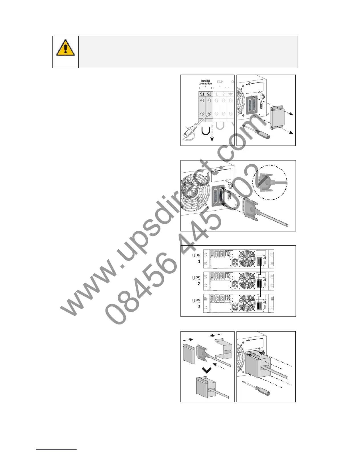
2. Remove jumper S1 - S2 from parallel
connection terminals on the power unit
terminal block (fig. 3.4.2.a).
3. The parallel cable connection slot is at the
rear of the power unit. Remove terminal
cover (fig. 3.4.2.b).
4. Connect the cable provided with the UPS
(fig. 3.4.2.c).
5. One cable connects two UPS in parallel.
To connect a third UPS into the parallel
system, repeat the process as above (fig.
3.4.2.d).
6. Remount the cover with the additional
metal part included in the unit shipping
box (fig. 3.4.2.e/f).
7. For a quick start of the system proceed
with section 4.2.2.
fig. 3.4.2.a fig. 3.4.2.b
fig. 3.4.2.c
fig. 3.4.2.d
fig. 3.4.2.e fig. 3.4.2.f
 Loading...


