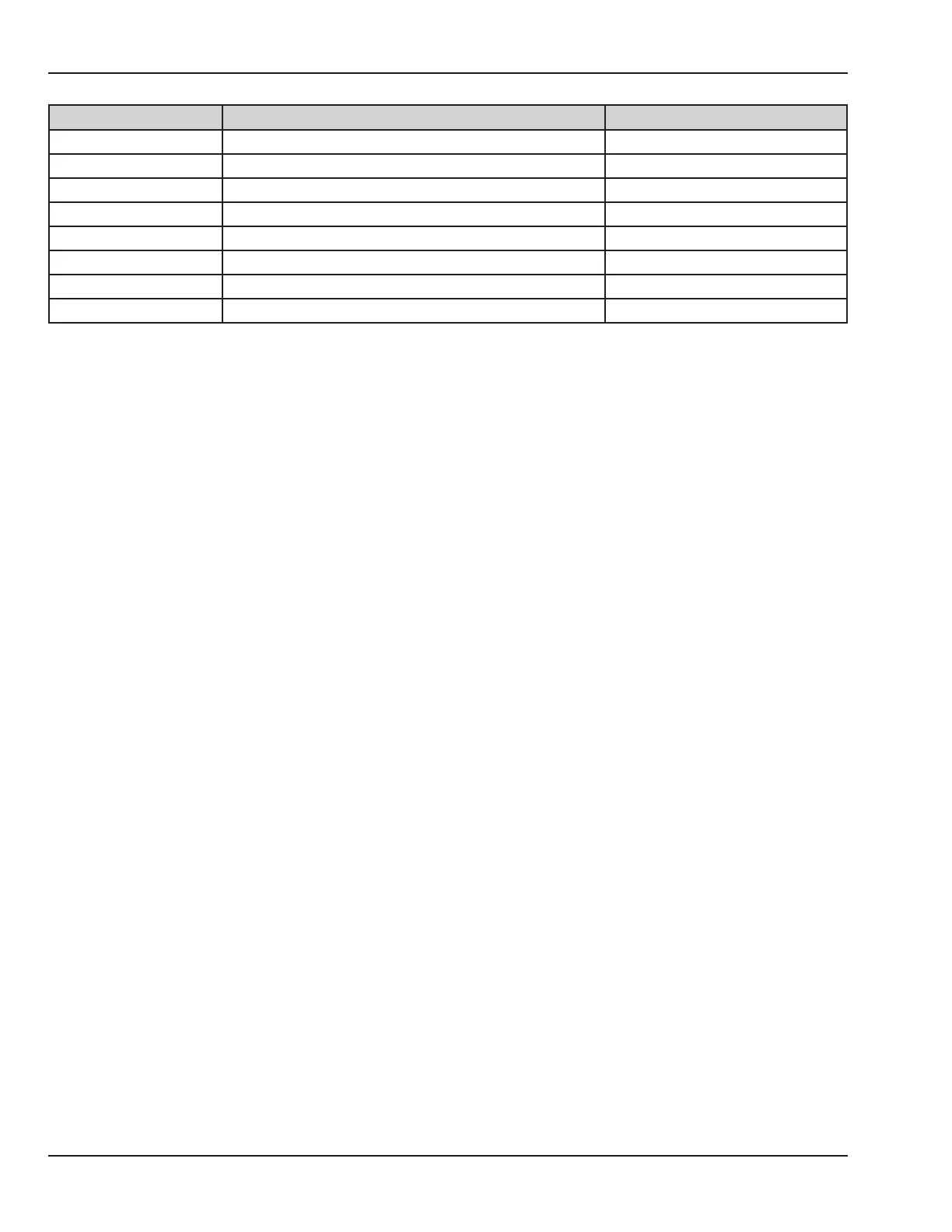
Qty. per assy. Description Part Number
3 Screw, M3 X 8, Phillips head, Teon coated 6600-1255-401
4 Screw, M3 X 10, Phillips head, Teon coated 6600-1255-402
4 Screw, M3 X 12, Phillips head 6600-1255-403
2 Screw, M3 X 16, Phillips head 6600-1255-404
4 Spacer, .125 ID 6600-1779-500
1 Ramp block 6600-1777-500
1 Heater mount 6600-1291-500
1 Button, reservoir switch 6600-1298-500
5.12.1 Tips for Repairing an Old Style Unit
Some of the hex head screws may be dicult to remove. To minimize the chances of stripping the heads, be
sure that the 1.5 mm Allen key you are using is not worn, and is not a ball head style. If you strip the heads,
you may need to drill them out. If you drill out the heads, you may need to replace the ramp block and/or the
heater mount if you have diculty in removing the body of the screw.
5.12.2 Disassembly
1. Remove the humidier reservoir.
2. Remove the 6 screws that secure the wire raceway cover and remove the cover.
3. Remove the chassis cover. (Refer to section 5.9.1.)
4. Disconnect the 3 electrical connectors.
5. Remove the 2 screws on either side of the heater assembly.
6. Remove the heater assembly.
7. Use a 2mm hex key to remove the 2 screws from the reservoir switch and remove the switch.
8. Remove the 4 screws that secure the top bracket. Back the bracket o feeding the wire harnesses through
as you remove it.
9. Remove the top gasket, feeding the wire harnesses through as you remove it. The thermostat wire harness
can slide through the slots in the gasket.
10. Remove the 4 screws in the heater mount and remove the bottom bracket.
11. Remove the socket head cap screw next to the add water thermostat, then remove the bottom gasket,
insulating cylinder, and protective insert.
134 6600-0343-000 104 © 2001 by Datex-Ohmeda, Inc.. All rights reserved.
Chapter 5: Repair Procedures

 Loading...


