1 2
DOWN
1
2
3
4
5
6
PHASE
NEUTRAL
+5 V
+12 V
GND
AC GND
+5V
+5V
+12V
GND
GND
1
2
3
4
5
P
N
G
UP
1 2
1
2
3
4
5
P
N
G
P
N
G
BT1
BATTERY
12
1
2
3
4
5
DOWN
13
24
P
N
G
230V
1
2
3
4
5
6
1 3
2 4
1
2
3
4
5
115V
1
2
3
4
5
6
1
4
3
2
5
6
7
8
UP
6600-0736-701
white
6600-1024-600
white
black
6600-0736-702
6600-0746-700
violet
black
black
6600-0707-700
red
red
Left/West
blue
Right/East
black
6600-0744-700
Ebase / Hood
Transformer
orange
black
red
yellow
red
6600-0227-850
Standby Switch
brown
Configuration Plug Group 1
To J44 on
Relay Board
To J52 on
Relay Board
To J43 on
Relay Board
To J47 on
Relay Board
6600-0748-7016600-0748-702
Configuration Plug Group 1
blue
6600-0800-700
orange
Relay Board
white
Power Supply
yellow
black
6600-0221-850
red
black
6600-0708-700
red
brown
To J41 on
To J48 on
green
Relay Board
Power Switch/
Circuit Breaker
6600-0583-600 (X3)
blue
6600-1006-600
brown
Outlets
6600-1014-601 (9 Amp, 230V)
6600-1014-602 (12 Amp, 115V)
6600-0562-603 X2
Line Filter
6600-0731-700
Circuit Breakers 3.5A.
Relay Board
To J51 on
Phase
Neutral
Sec A 14.6vac
Sec A 14.6vac
Sec B 14.6vac
Sec B 14.6vac
Phase out
Phase in
V charge out
V charge in
V battery
GND
red
Relay Board
brown
red
black
To J35 on
UPHOOD
UPHOOD
DOWNHOOD
brown
DOWNHOOD
GND
GND black
Ebase / Hood Transformer
Standby Switch
Power Supply
Mains Outlets
includes wiring to outlets
Hood Hand Control
Hood Hand Control
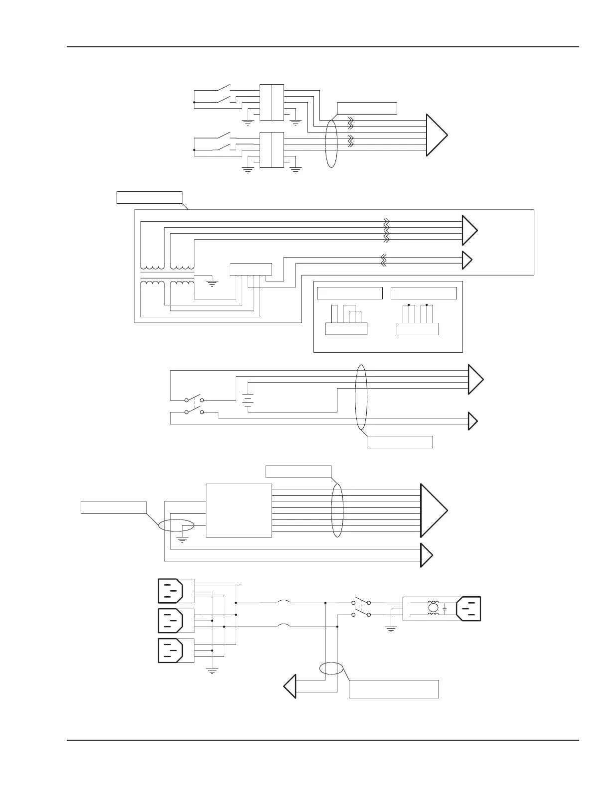
Figure 6-45 Wiring Diagram: Electrical Enclosure
When checking for
the secondary voltage
5 and 12 VDC from
the power supply to
the relay board J 41,
make sure the power
cord is connected
and both the breaker
on the back and the
switch on the front
panel are in the ON
position.
120VAC into relay board and out
to power supply. If in good and
out missing check fuses on relay
board.
© 2001 by Datex-Ohmeda, Inc.. All rights reserved. 6600-0343-000 104 223
Chapter 6: Illustrated Parts

 Loading...


