MA-025 – DGA 900 Operator Guide – Rev 2.0 12-Apr-19 Page 78 of 92
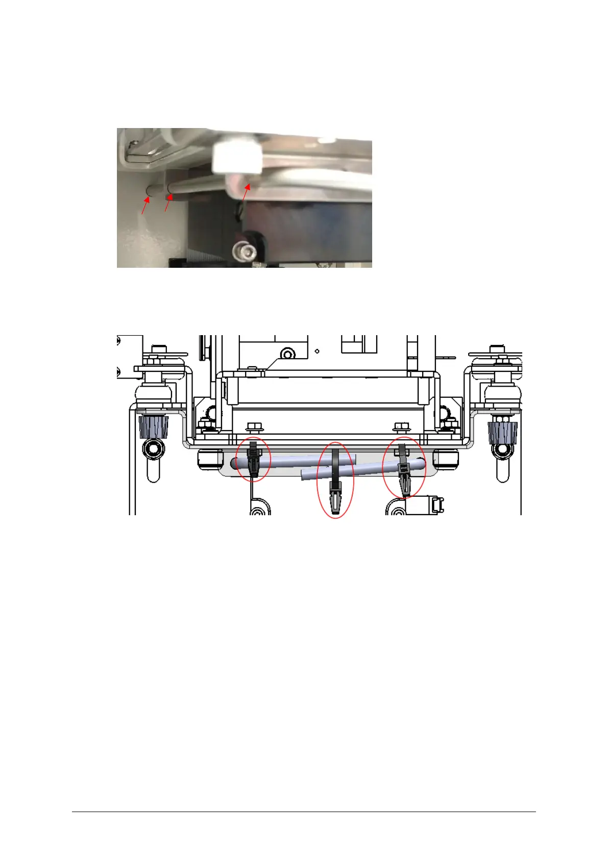
▪ Ensure that each pin end is fully inserted into the hole in the back wall of the enclosure
as shown in Figure B-9.
Figure B-9: PGA lock – pin to enclosure hole
▪ Use three cable ties to secure the pins to the metal bracket at the appropriate holes as
shown in Figure B-10.
Figure B-10: PGA lock – pins and locking bracket secured with cable ties
The transportation PGA lock is now engaged rendering the PGA anti-vibration mounts
inactive. After the product is removed, ensure that it is stored in an upright position. Note:
Any remaining oil in the pipework should be drained into a suitable container.

 Loading...


