Kilsen KFP-CF Series Operation Manual 3
Control panel overview
This topic provides an introduction to the control panel interface, operator controls,
and indicators.
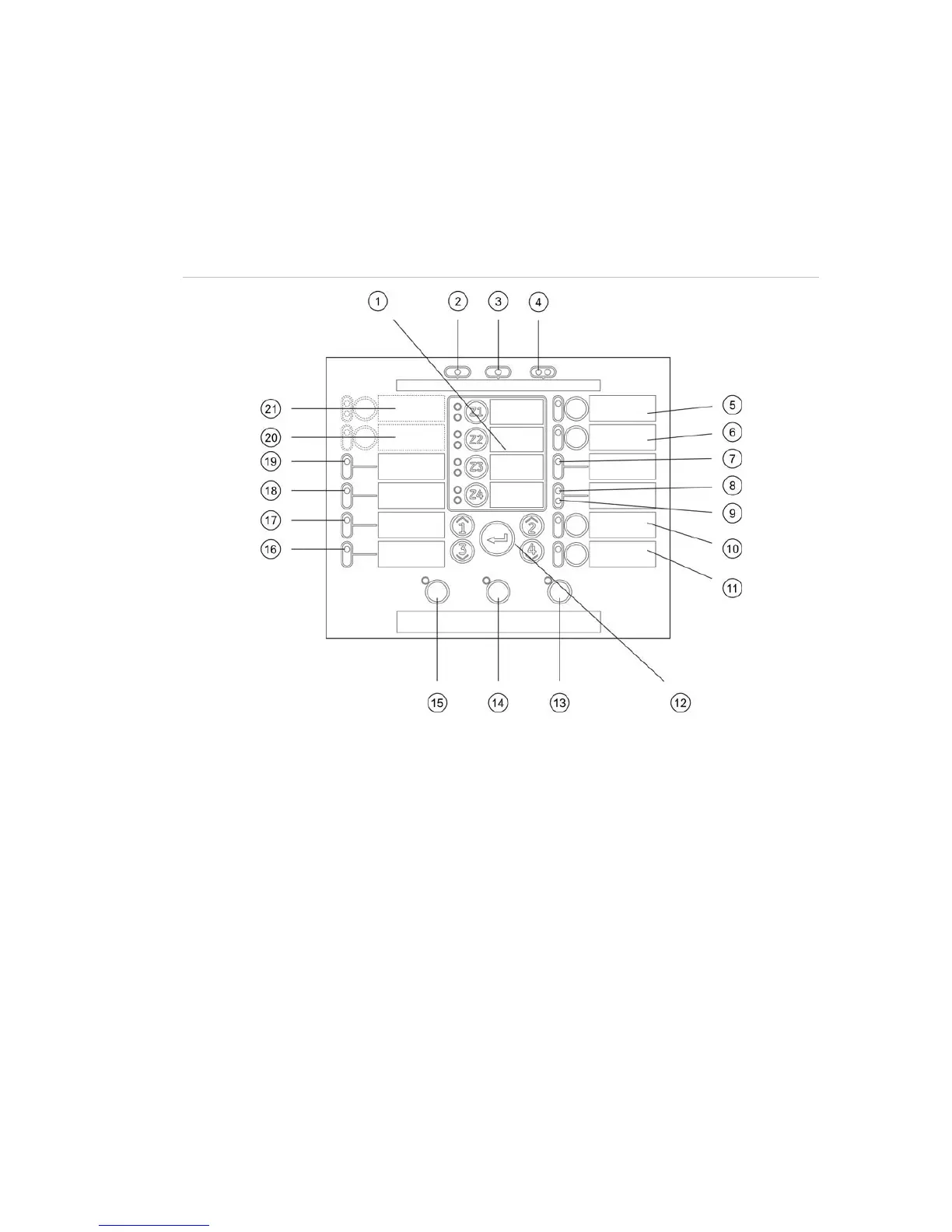
User interface for two- and four-zone control panels
Figure 1: User interface for two- and four-zone control panels
1. Zone buttons and LEDs (Z1, Z2, etc.)
2. Supply LED
3. General Fault LED
4. General Fire Alarm LEDs
5. Sounder Fault/Disable/Test button
and LED
6. Sounder Delay button and LED
7. Network Fault LED
8. Service Detector LED
9. Expansion I/O Fault/Disabled LED
10. General Disable button and LED
11. General Test button and LED
12. Configuration controls
13. Reset button and LED
14. Panel Silence button and LED
15. Sounder Start/Stop button and LED
16. System Fault LED
17. Out of Service LED
18. Earth Fault LED
19. Supply Fault LED
20. Fire Routing Delay button and LED
21. Fire Routing Start and
Fault/Disable/Test button and LEDs
Note: Two-zone control panels do not include fire routing.
 Loading...