GE_UPS_ISG_LPS_3UL_20K_30K_2US_V010.docx
Installation Guide LP33 Series 20 & 30 UL S2
4.9 ELECTRICAL CONNECTIONS
WARNING !
The connections to and from the UPS must be executed by QUALIFIED PERSONNEL
ONLY. Refer to the “Safety Rules - Installation” described on page 6.
4.9.1 Common input utility
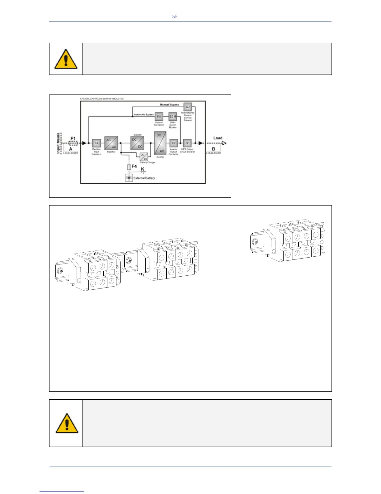
Fig. 4.9.1-1 Common input utility
Common input utility
The UPS delivered in standard
version has common input utility.
Only one input line (F1) supplies
both rectifier and bypass input
terminals.
Bear in mind that when the utility
fuses are opened there is a supply
failure to the rectifier as well as to
the automatic bypass and manual
bypass.
Fig. 4.9.1-2 Terminals for common input mains
X1 Utility 1 - Input utility connection
L1 = Rectifier + Bypass Phase A
L2 = Rectifier + Bypass Phase B
L3 = Rectifier + Bypass Phase C
N1 = Utility Neutral PE = Main Ground
X3 Load - Output load connection
L1 = Load Phase L1
L2 = Load Phase L2
L3 = Load Phase L3
N2 = Load Neutral PE = Load Ground
Max. rating X1, X2 and X3 terminals:
Connect wire to the Terminals using appropriate tools and appropriate torque shown in Section 4.8.1.
NOTE !
For UPS correct operation, the input utility phase rotation must be clock-wise.
Inside the UPS, all neutrals N1 and N2 are connected together.
This UPS is designed to operate in a wye-configured electrical system with a solidly
grounded neutral.
Load
X3
L1
L2
L3
N2
PE
LPS33U_040-080_Connection common_02US
Utility 1
X4
Battery
X1
L1-1
L2-1
L3-1
N1
PE
-
0
+
PE
 Loading...


