GE_UPS_ISG_LPS_3UL_20K_30K_2US_V010.docx
Installation Guide LP33 Series 20 & 30 UL S2
6 OPTIONS
6.1 TOP ENTRY CABLES CABINET
Fig. 6.1-1 Cabinets positioning
Top Entry Cables Cabinet
Allows the connection of input and output cables from the top of the UPS.
The “Top entry cables cabinet“ must be placed on the right side of the UPS
cabinet as illustrated in drawing Fig 6.1-1.
The “Top entry cables cabinet“ is accessibly from right side and front side
(see panel “A” and panel “D” in the Fig. 6.1-2).
6.00”x27.64x74.50” / 152x702x1892mm
Screw torque specifications
M8x16 Tensilock: 222Lb-in / 25Nm
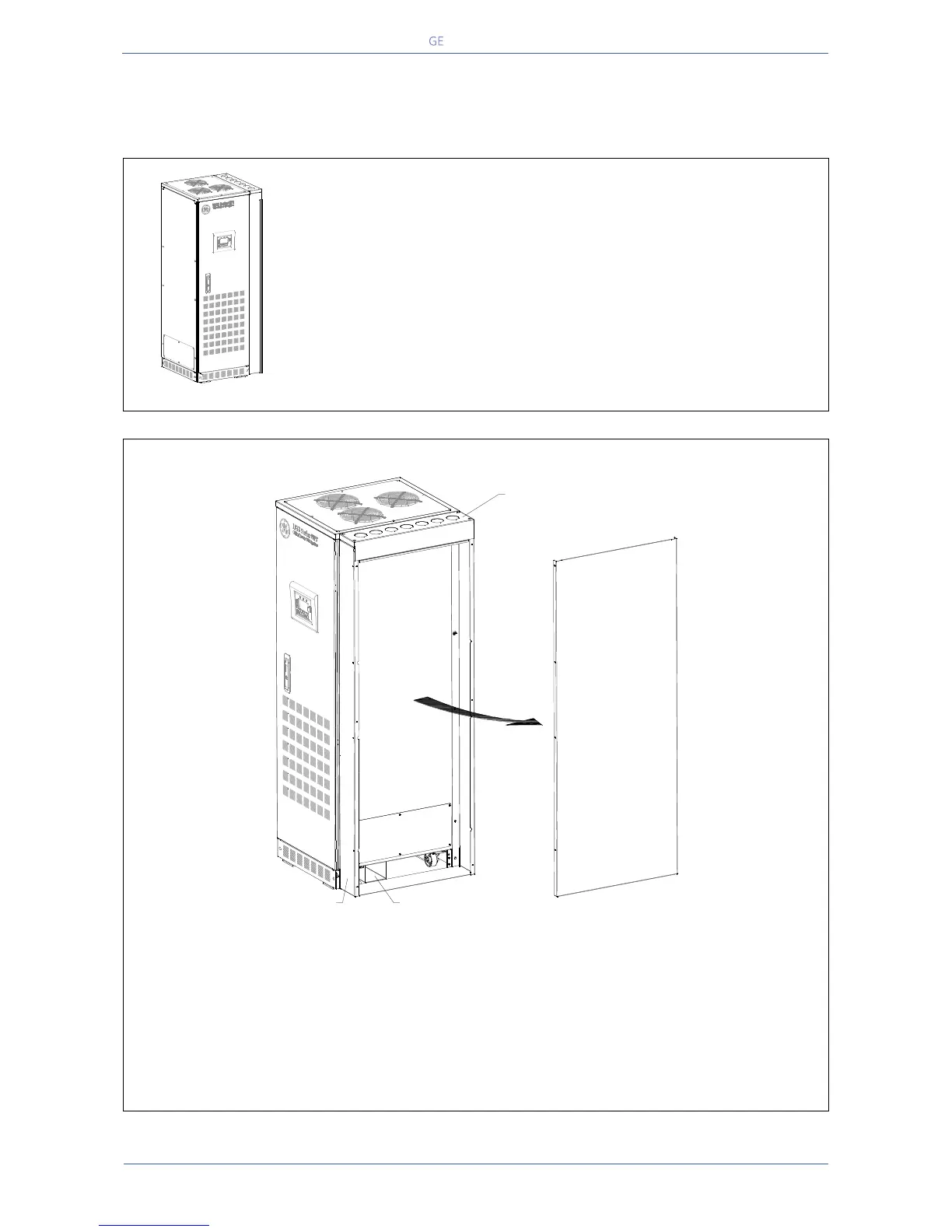
Routing of cables for Top Entry cabinet
Fig. 6.1-2 Routing of cables for Top Entry cabinet
- Remove side panel “A” to gain side access to the UPS for top cable entry.
- Knock out appropriate holes in top plate “B” for top cable entry.
- Terminate conduits to top panel “B”.
- Route wires into the UPS cabinet from top panel “B” through the input/output cable opening “C”
shown on the drawing.
- For electrical connections of the UPS please refer to Section 4.9.
- Once all electrical connections have been made, reinstall side panel “A”.
LPS33U_020-030_S2_UPS+TEC_GE_01
A
LPS33U_020-030_S2_UPS+TEC_Assembling_GE_02
B
C
D