GE_UPS_ISG_LPS_3UL_20K_30K_2US_V010.docx
Installation Guide LP33 Series 20 & 30 UL S2
WARNING !
Connections described in this chapter shall be done only by a TRAINED PERSON or
SERVICE ENGINEERS.
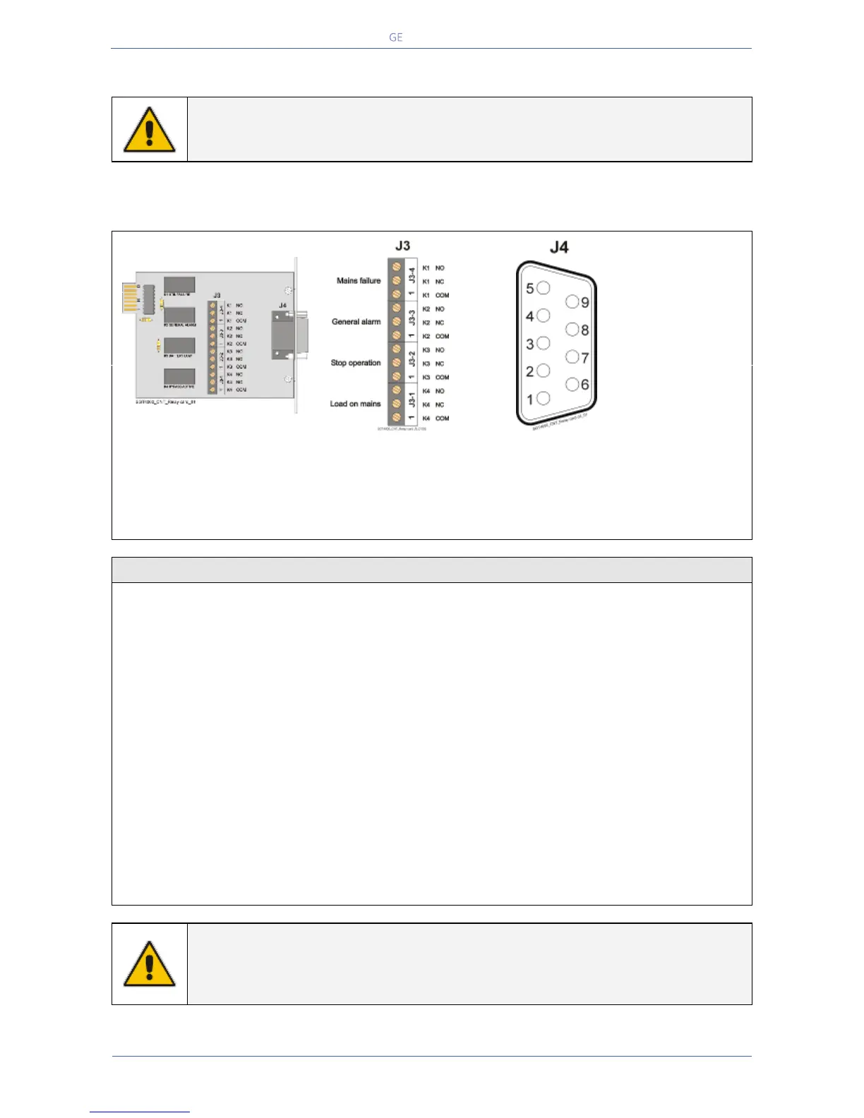
The Relay Card, allows the programming of 4 output channels on dry contacts, which can be read on
either terminal J3 or plug J4 (sub - D - male 9 pin).
Voltage free contacts: Max.: 60Vdc or 30Vac / 0.5A
Min. signal level: 5Vdc / 5mA
Output signals on voltage-free contacts
On terminals J3 or J4 connector 4 of the following 28 signals can be selected from the display
(access only with password): SETUP / SETUP / LEVEL 2: SERVICE.
Inverter-mains not in sync
EPO (Emergency Power Off)
NOTE !
The function GEN-ON is not available on the Relay Card.
In case this function is needed, the optional Customer Interface card must be
installed (see Section 5.4.1).
 Loading...


