GE_UPS_ISG_LPS_3UL_20K_30K_2US_V010.docx
Installation Guide LP33 Series 20 & 30 UL S2
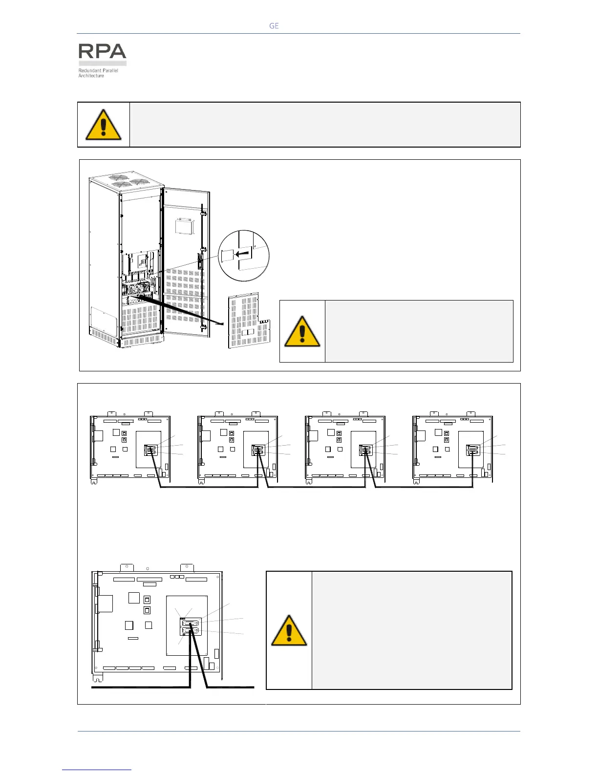
4.9.4 RPA Parallel System - Control bus connection
WARNING !
This operation must be performed by trained personnel before the initial start-up
(ensure that the UPS installation is completely powered down).
Fig. 4.9.4-1 Access to the RPA board
Access to the RPA board
1 - Open the front door “A” of the UPS cabinet.
2 - Remove the front panel “B”.
3 - Remove with appropriate tool the metallic
window “C” from the metal screen “D”.
NOTE !
Put in place the front screen “A”
paying attention to not damaging the
control bus cables.
Fig. 4.9.4-2 Bus connection RPA Parallel System
Bus connection RPA Parallel System
Connect the control bus cable between the parallel units as indicated in the diagram Fig. 4.9.4-2.
Provide that the connectors J3 and J4 are properly fixed with the included screws.
Fig. 4.9.4-3 Connection to Board P16
NOTE !
The jumper JP1 - JP2 - JP3 must be
removed only on the intermediate units,
where the connectors J3 and J4 are both
inserted.
Do not insert or remove J3 and J4 from
the board “P16 - Connector adapter RPA”
when the Parallel System is operating.
A
B
D
C
LPS33U_020-030_S2_RPA connection_01
LPS33U_030-040_RPA connection_GE_02
J4
J3
LP 33 Series
1
P1
P13
P34
P1
J3
P13
J4
P34
LP 33 Series
2
J3
P1
P13
J4
P34
LP 33 Series
3
P34
J4
J3
P1
P13
LP 33 Series
4
P1
J3
P13
J4
P34
LPS33U_030-040_RPA connection_03
JP1 JP2
JP3