Modifications reserved Page 17/66
OPM_LPS_3UO_80K_M10_1US_V010.doc User Manual LP33 Series 80 & 100 UL S1
4.4 UPS PARALLELED ON THE SAME BATTERY
NOTE !
A parallel system with a Common Battery for two or more UPS, requires a particular
installation and adequate setting of some parameters, (accessible only through
password), and can therefore only be done by a QUALIFIED GE ENGINEER.
Usually each UPS Unit runs with its own Battery.
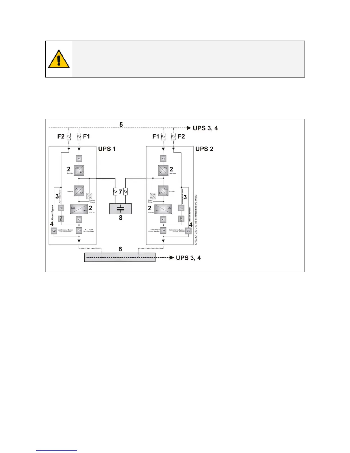
In case of parallel units running with a Common Battery (max. 4 UPS - see Fig. 4.4-1), the sharing circuit
between the individual UPS is integrated in the communication bus of the system in order to assure an
equal sharing of the Rectifiers output currents.
Fig. 4.4-1 Diagram RPA system with UPS on common battery
1 –
Rectifier
Inverter
Automatic Bypass
Manual Bypass
Mains Power
Load Bus Bar
External Battery Protection
Battery
Pay attention to the following recommendations:
• The units delivered for this functioning mode need a special parameter setting, so they must be
prepared in advance before the installation.
• The installation must be performed only with the UPS system completely shut down.
• The AC Rectifiers input power (5) must be the same, with clockwise phase rotation for each unit.
• Each Rectifier must be set for the same floating DC voltage and the same Battery current limitation.
• It is mandatory to install the fuses / MCB (7) on each line connecting the Rectifiers to the common
Battery for maintenance / safety reasons (see Section 4.7.2).
• In case a unit must be powered down for maintenance, switch-OFF the concerned unit before
opening the DC fuses / MCB on the Battery line (7).
• If an emergency generator set supplies the UPS, and the free contact “Generator ON” is connected
to the Customer Interface, connect a separate NO free contact on each parallel unit.
• Do not connect the temperature sensor for automatic battery floating voltage compensation.
• Do not enable the function Boost charge.
 Loading...