Modifications reserved Page 60/66
OPM_LPS_3UO_80K_M10_1US_V010.doc User Manual LP33 Series 80 & 100 UL S1
7.2.5 Reconnect a UPS unit to a Parallel System
WARNING !
Before connecting hazardous voltages, make sure that:
• The connection to the electrical system has been performed by qualified personnel;
• The equipment frame has been correctly grounded to the main earth;
• Make sure that utility input protection is removed;
• All the panels removed to allow the UPS connection have been correctly reinstalled;
• The UPS switches Q1 and Q2 are open (Pos. 0);
• The “Battery Breaker” of the battery cabinet is OFF (Pos. O).
This procedure must be performed when the load is supplied by the other units of the UPS Parallel
System and an additional unit must be switched ON and connected to the parallel bus in order to share
the load with each other.
This unit must be completely switched OFF and not powered.
1.
Switch ON (Pos. I) the utility voltage from the input distribution (both rectifier and bypass if
separated) on this UPS unit.
Overall test results
Test1 OK Test7 OK
Test2 OK Test8 OK
Test3 OK Test9 OK
Test4 OK Test10 OK
Test5 OK Test11 OK
Test6 OK
The UPS performs a SELFTEST.
A successful termination of the tests will be indicated with Overall
test results “OK”.
Commissioning cannot be continued should one or more tests result
to be negative.
Please contact in this case your Service Center.
2. Close output switch Q1 (Pos. I ) on this UPS unit.
`Home\Meter
BOOSTER
f : 60.0 Hz
L1 : 120 V
L2 : 120 V
L3 : 120 V
Vp : 210 V
Vn : 210 V
Verify on this UPS unit, selecting the screen METERING/BOOSTER/Vp
and Vn, that the booster voltage has reached about 210 Vdc.
3. Switch ON (Pos. I) the “Battery Breaker” of the battery cabinet on this UPS unit.
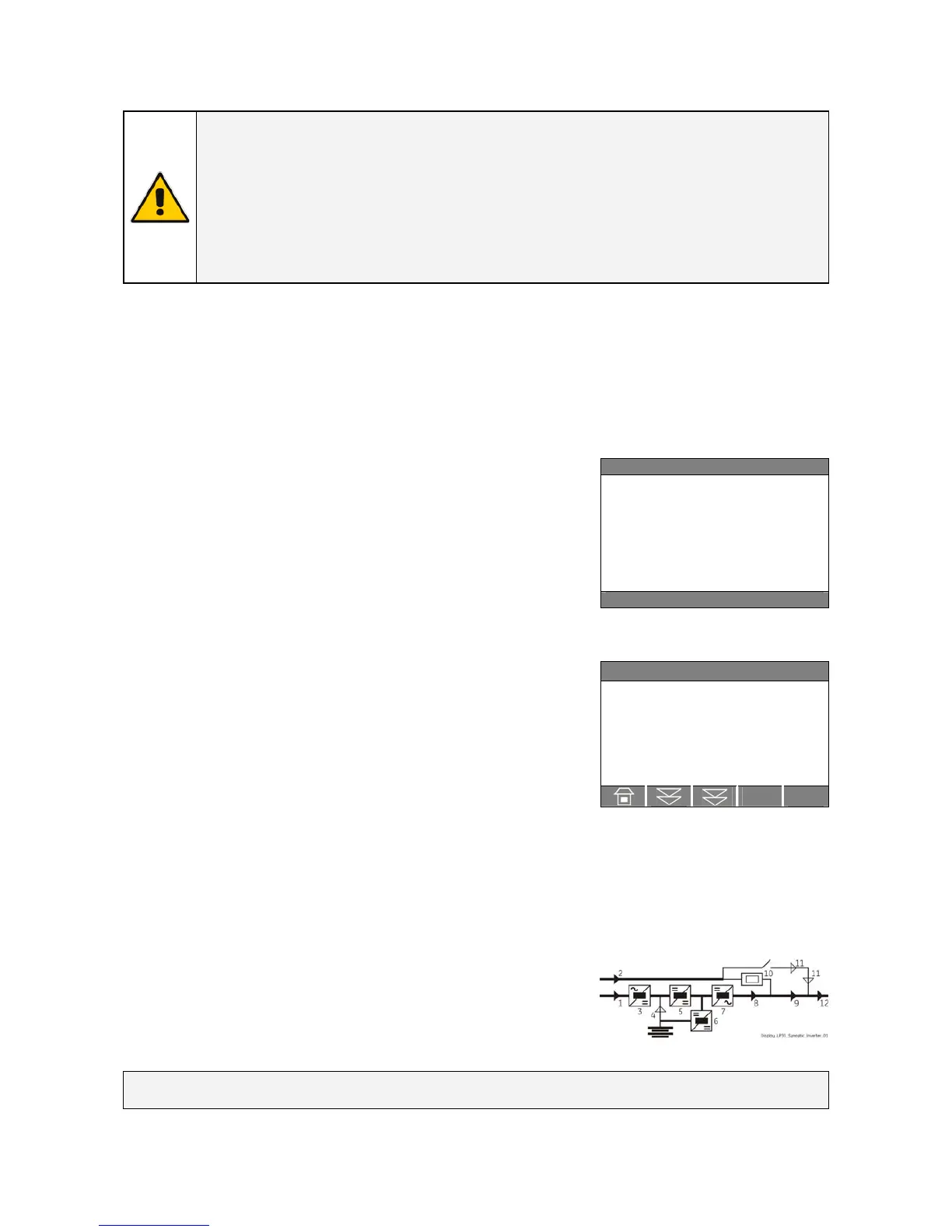
4. Insert the inverter by pressing “Inverter ON” ( I ) key on this UPS unit.
When the inverter will be synchronized, the unit will be
automatically connected with the parallel bus bar and the load will
be shared with the other units.
LED Alarm turns OFF and the LED Operation must be lit.
The synoptic diagram, on all UPS units, must display the status
“LOAD SUPPLIED BY INVERTER”.
 Loading...