9
To fit Door Interlock
A door interlock mechanism may be fitted inside the cassette
on the right for L/H hinged door or left for R/H hinged door.
Specify whether door is L/H or R/H hinged when ordering.
Fig. 34
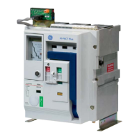
Interlock Packs
Each pack contains - an interlock lever, a helical spring,
washers and circlips, (Fig. 34 shows both L/H and R/H sets). A
door bracket is also included (Fig. 35).
Fig. 35
Assembly
Place spring over the spring pin protruding from cassette side
plate. Position interlock lever as shown. Ensure one end of
spring locates below nut and the other rests over small boss
on lever.
Holding lever in position - insert a circlip into the groove in the
spring pin then fit two washers over fulcrum boss followed by a
circlip to fix (Fig. 36).
Fulcrum boss with End of spring locates
2 washers & circlip below nut
Fig. 36
End of spring fits Spring over spring pin
above boss on
inside of lever Circlip
Door bracket location detail below is for left hand hinged
switch board doors (Fig. 37). Drill two holes in the door for M5
clearance.
Door bracket location detail below (Fig. 38) is for right hand
hinged switch board doors. Drill two holes in the door for M5
clearance.
Busbar/Cable Earthing
Optional pack to enable earthing of circuit breaker terminals on
busbar or cable side contains:-
• Isolating contact (cluster) pliers for removal of the main
isolating contacts.
• Earthing bar with spring pressured earth contact. The bar is
reversible to fit top or bottom terminal sets.
• Necessary fixing bolts and washers.
• Anti-trip plate.
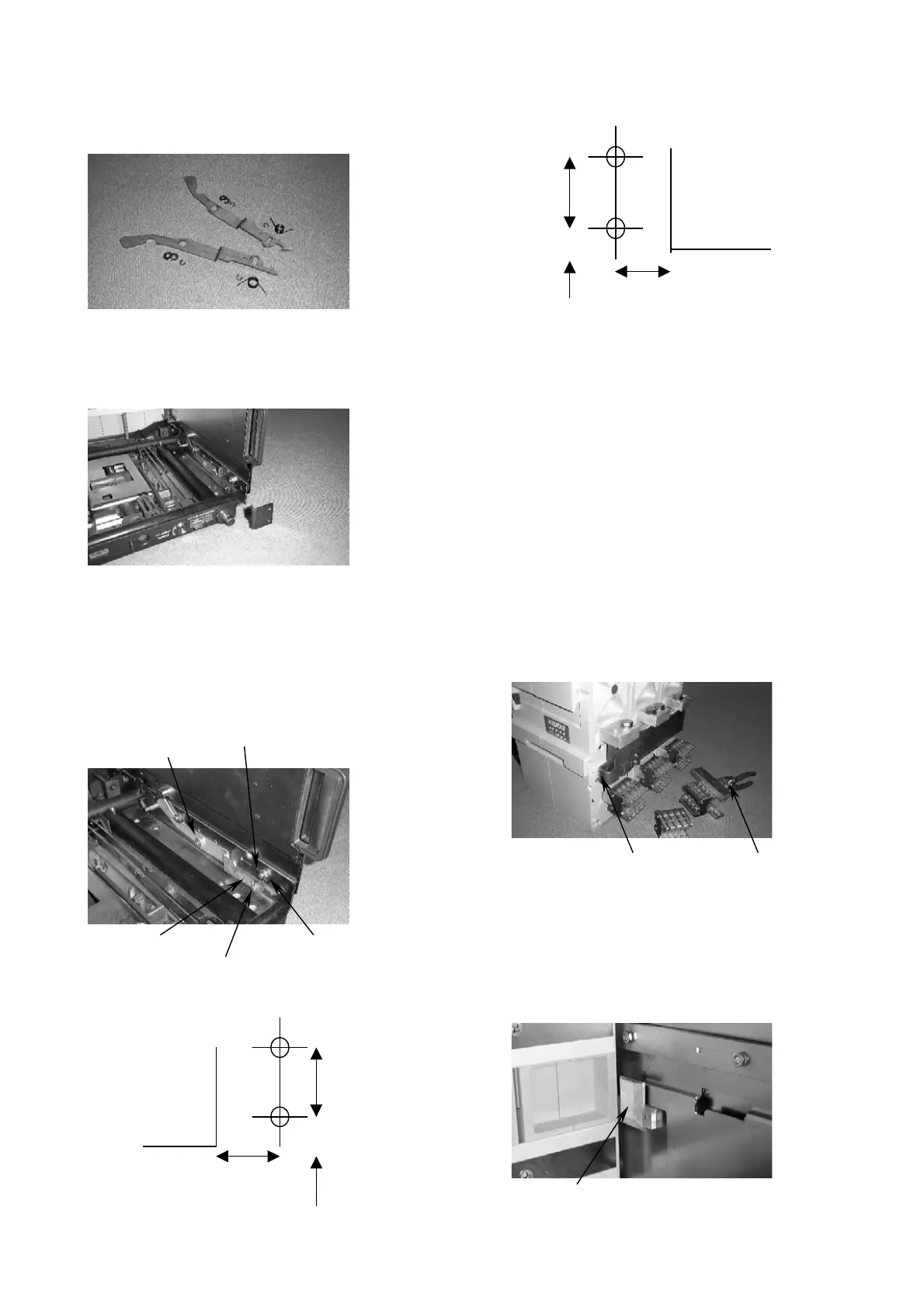
To earth the upper contact set:
(a) Remove the three upper contact clusters at the rear of the
circuit breaker, using the cluster pliers provided (Fig. 39).
(b) Position earthing bar below the three exposed terminals and
loosely tighten the M10 bolts (into the tapped earthing bar; one
bolt per phase. Tighten to 30Nm.
Note: The spring loaded earthing contact should be facing left
when viewed from rear (Fig. 39).
Fig. 39
To earth the lower terminal set:
a) Remove lower cluster contacts, reverse the earthing bar so
that the M10 tapped holes point downwards, apply bolts and
washers as above.
b) The spring loaded earthing contact, still facing left, will locate
in the same position whether upper or lower terminals are
earthed and will engage with a fixed earthed contact block in
the cassette when the breaker is racked to the CONNECTED
position (Fig. 40).
Fig. 40
RH hinged
Door cut-out
21mm
8mm
F1, 3P & 4P – 41.5
F2, 3P & 4P – 101.5
L.H hinged
Door cut-out
21mm
F1, 3P – 27.5
F1, 4P – 127.5
F2, 3P – 57.5
F2, 4P – 187.5
8mm
Fi
. 37
Fig. 38
Fixed earthing contact in cassette
Cluster pliersSpring loaded earthing contact
 Loading...