33
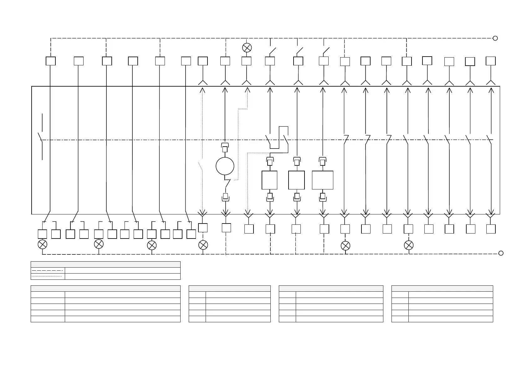
SECTION 3 M-PACT Wiring Diagram
Key
Customer Supplied External Wiring (example)
Optional Factory Internal Wiring
Terminal References Key Key Key
B1 to B16 Automatic disconnect L.T. Blocks LP1 Disconnected indication CC Closing coil LP6 ACB ON indication
C1 to C16 Automatic disconnect L.T. Blocks LP2 Test indication UVI Undervoltage release LP7 Closing springs charged indication
D1 to D6 Carriage switch blocks for disconnected position LP3 Connected indication UVT Time delayed undervoltage release ML Charging motor limit switch
D7 to D12 Carriage switch blocks for test position LP4 ACB tripped indication AL M-PRO trip alarm (N/O) M Closing spring charging motor
D13 to D18 Carriage switch blocks for connected position LP5 ACB OFF indication B ACB main contacts ST Shunt trip
UVI
or
UVT
ST CC
M
ML
L
B
LP1
LP5
LP6
LP7
+ve +ve
+ve
OFF
switch
ON
switch
emer-
gency
OFF
D1
D2 D3
D4
D5 D6
D7
D8 D9
D10
D11 D12
D13
D14 D15
D16
D17 D18
B7
B8
B9
B10
B2 B12 B14 B16
B1 B11 B13
B15
LP4
LP3
LP2
C1
C3
C7
C5 C15
C9
C11 C13
C2 C4 C6 C10C8 C12 C14 C16
 Loading...