Hot Gas Path Inspection — Disassembly ProceduresInspection and Maintenance — GEK 107048
HGP-D-9
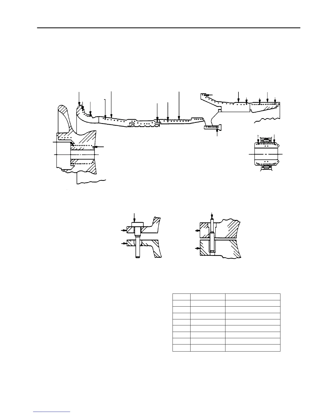
Figure HGP-D.4. Guide Pin Locations.
Guide
Pin
Guide
Pin
Upper Half
Bearing Cap
Lower Half
Bearing Cap
Upper Half
Casing
Lower Half
Casing
No. 1 Bearing
Lower Half Turbine Casing
No. 2 Bearing
55
99
Inlet
Casing
Exhaust
Frame
Turbine
Casing
6
3
Discharge
Casing
71
1
Compressor
Casing
88
4
4
NOTES: Guide Pins Found In
Tool Kit, Major
Disassembly
Guide Pins Are Used In
Body Round Stud Holes
of Casings and Dowel Holes
of Bearing Caps.
ITEM GUIDE PIN WHERE USED
1 248A4880 P4 Compressor Casing
3 295A9609 P2 Turbine Casing
4 295A9601 P1 No. 1 Bearing Cap
5 295A9601 P2 No. 2 Bearing Cap
6 295A9609 P3 Turbine Casing
7 295A9609 P1 Discharge Casing
8 295A9600 P1 Inlet Casing
9 295A9601 P3 EXHAUST FRAME
 Loading...


