– 29 –
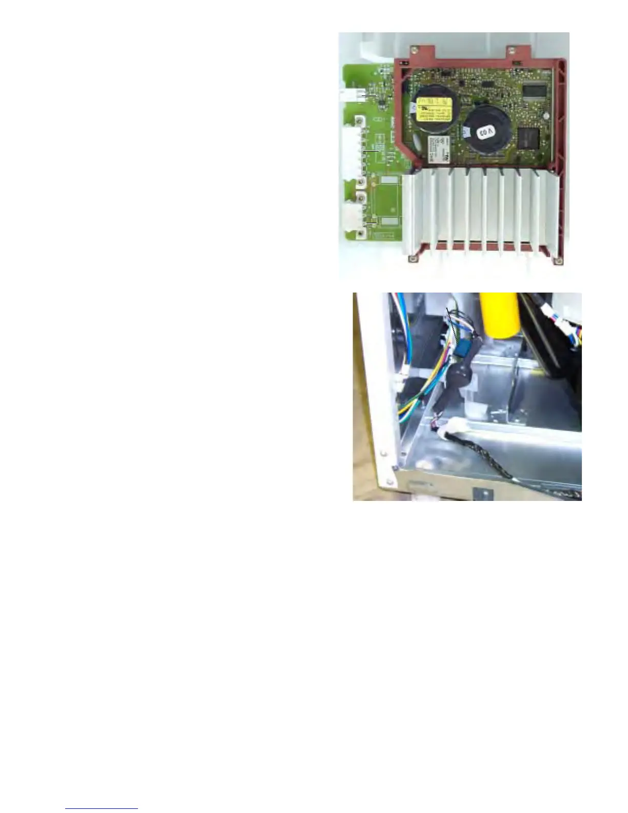
Snubber
Snubber
CN8
CN9
CN10
Speed Sensor
The speed sensor is comprised of a sensor mounted on the brake assembly and a set of magnets
mounted on the transmission. The sensor remains stationary, but the magnets rotate with the basket.
As the transmission rotates, the magnets pass the sensor and a signal is sent to the electronic control
board. The electronic control board activates the lid lock and calculates brake stop time based on this
signal.
When speed sensor input indicates that the basket is spinning at 50 rpm, the control will engage the lid
lock. If the speed sensor fails or an open occurs in the wiring, the lid lock will not engage; however,
normal function will continue, provided the lid is not raised during spin. If the lid is raised during a spin
cycle for more than 5 seconds, the electronic control board will limit the high speed spin to a maximum
of 630 rpm and a lid lock error code will be logged. Spin speed will continue to be limited to 630 rpm
until the lid lock error is cleared using service mode.
Speed sensor input is also used by the electronic control board to calculate brake stop time. If, within a
1-year period (400 washes), the control board detects 3 stop times in excess of 25 seconds, the control
will determine that a catastrophic brake failure has occurred. The unit will immediately be disabled and
will display error code E43 on the Digital Seven Segment Display (DSSD). The unit will power up, but
no cycle selection will be available. The unit will remain disabled until the error code is reset using
service mode.
Inverter
The inverter converts line-in, single-phase, 60 Hz,
120 VAC into 3-phase, varying frequency,
230 VAC. The inverter controls motor speed,
torque, and direction. It also provides motor over-
current and thermal overload protection.
Motor speed is regulated by Pulse Width
Modulation (PWM). PWM outputs voltage to the
motor in pulses rather than an uninterrupted flow.
This pulsing produces effective voltage being
received at the motor, which is equivalent to a
reduction in voltage.
Motor torque is adjusted throughout the speed
range by varying the pulse width modulated
voltage to the motor. The inverter monitors the
motor current and uses this information to
calculate and make motor torque adjustments.
This eliminates the requirement of a clutch.
Direction of rotation is changed by the inverter
reversing polarity.
The inverter housing is mounted to the side of the
cabinet with double-sided tape and to the base of
the unit by 2 tabs which fit into slots. Access is
obtained by removing the front panel.
The inverter wiring harness includes a snubber to
reduce EMI. A shorted snubber may cause a
failure to occur on the electronic control board
(see Electronic Control Board).
 Loading...