– 47 –
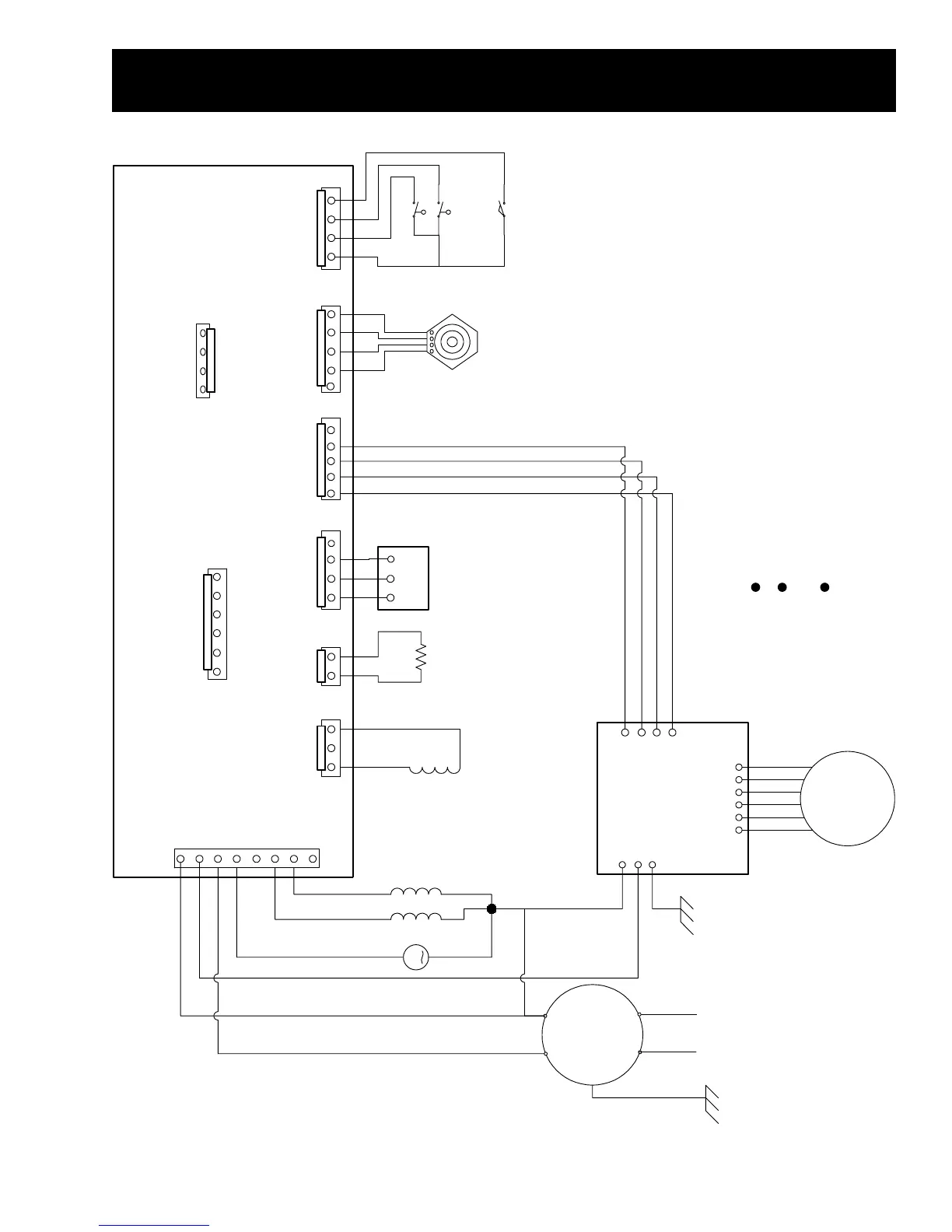
Schematic
H
O
T
C
O
L
D
M
P
U
M
P
321
LID LOCK POWER
J19
LID LOCK RETURN
L
I
D
L
O
C
K
123456
J5
DIGITAL GND
MODEL SEL 0
MODEL SEL 3
MODEL SEL 2
DIGITAL GND
MODEL SEL 1
1234
LID SWITCH
11
COM
LOW
12
HI
16
WATER
LEVEL
SWITCH
J8
LID SWITCH
PRESSURE SWITCH LOW
PRESSURE SWITCH HIGH
+12V
1
2
3
4
5
6
7
8
J1
NEUTRAL
VSD
L1
PUMP
HOT H2O
COLD H2O
EARTH GND
VARIABLE
SPEED
MOTOR
CN10
234561
INVERTER
M
L1 N
FILTER
1
3
2
4
CN9
1
3
2
CN8
J6
12
50K Ohms
at 77∞F
WATER
TEMPERATURE
SENSOR
ANALOG GND
THERMISTOR
J2
5 4
RS485 - B
2
V(SENSE)
1
SENSOR GND
3
RS485 - A
U
ACCELEROMETER
1234
V(SENSE)
VERTICAL ACCL
RADIAL ACCL
SENSOR GND
5
J10
4
J3
DIGITAL GND
1
+12 V
2
ACC
3
321
SPEED SENSOR
123
V(SENSE)
SENSOR GND
4
SPEED SIGNAL
J20
EARTH GND
YR
CX
VX
YB
RX
WX
YX
BX
WX
BX
RX
VX
WX
BX
RX
WX
BX
NX
RX
WR
NW
RB
BX
TX
VX
YELLOW
RED
BLUE
WHITE
BLACK
GREEN
NOTE:
The switches are normally closed (with no water in the tub)
The schematic shows the washer with a full tub of water
and the lid open.
The motor should read approximately 6 ohms between
terminals 1, 2, and 3 (yellow, red, blue)
 Loading...