80018C_MSW_2400-2500-Profibus_1209_ENG
Page 13
5 USING PROFIBUS 2400/2500 INSTRUMENTS WITH SIEMENS STEP7
5.1 CONFIGURATION
Files 24000A40.gsd and 25000A40.gsd contain the information needed to operate a PROFIBUS DP Slave
instrument. These files have to be installed in SIEMENS Step7 programming environment in order to insert the
2400/2500 instruments in the PROFIBUS network hardware configuration.
1. Open the project hardware configuration.
2. Select Station/Close on the menu.
3. Select Instrument/Install new GSD file.
4. In the window, look for the file on the support on which it is saved (Floppy or Hard Disk).
5. Press Open.
6. The item “2500 HIGH PERFORMANCE CONTROLLER” (with file 25000a40.gsd) or “2400 HIGH
PERFORMANCE INDICATOR” (with file 24000a40.gsd) has now been added to the catalog. To find it,
expand the item “Profibus”, then expand the folder “Other field devices”, and finally expand “Controller.”
7. Reopen the project station configuration.
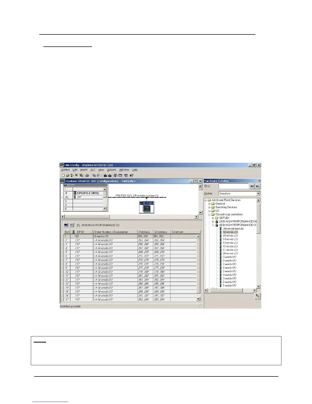
8. Drag the 2500 HIGH PERFORMANCE CONTROLLER icon with the mouse and drop it on the Profibus
bus line of the project. A new Profibus Slave will be created.
9. Assign the PROFIBUS node to the new Slave. The PROFIBUS node must conform to the one set on the
instrument by means of the rotary switch. The dedicated memory areas will appear automatically.
10. To select an element from the section “2500HIGH PERFORMANCES CONTROLLER”, according to the
number of word of data of process wished. The dedicated areas of memory will appear automatically.
The first 7 read bytes and the first 7 write bytes are called “Consistent,” and correspond to addresses
PEB256..PEB262; PAB256..PAB262 in the figure. The next bytes (PEB263..PEB294;PAB263..PAB294) represent
the contents of the instrument’s variables parameterized via the “DP Slave Properties” window.
Note:
If you decide to use both FC “CFG 2400_2500” (see par. 5.3.1) and FC “PD_2400_2500” (see par. 5.3.2) it is
necessary to check that the Hardware configurator assigned memory addresses close to all memory areas. In case
of “holes” or “jumps” in the sequence, manually assign the first address in an area known to be free. If FCs are
used, E addresses (inputs) must be equal to A addresses (output).
 Loading...