- 25 -
INSTALLATION
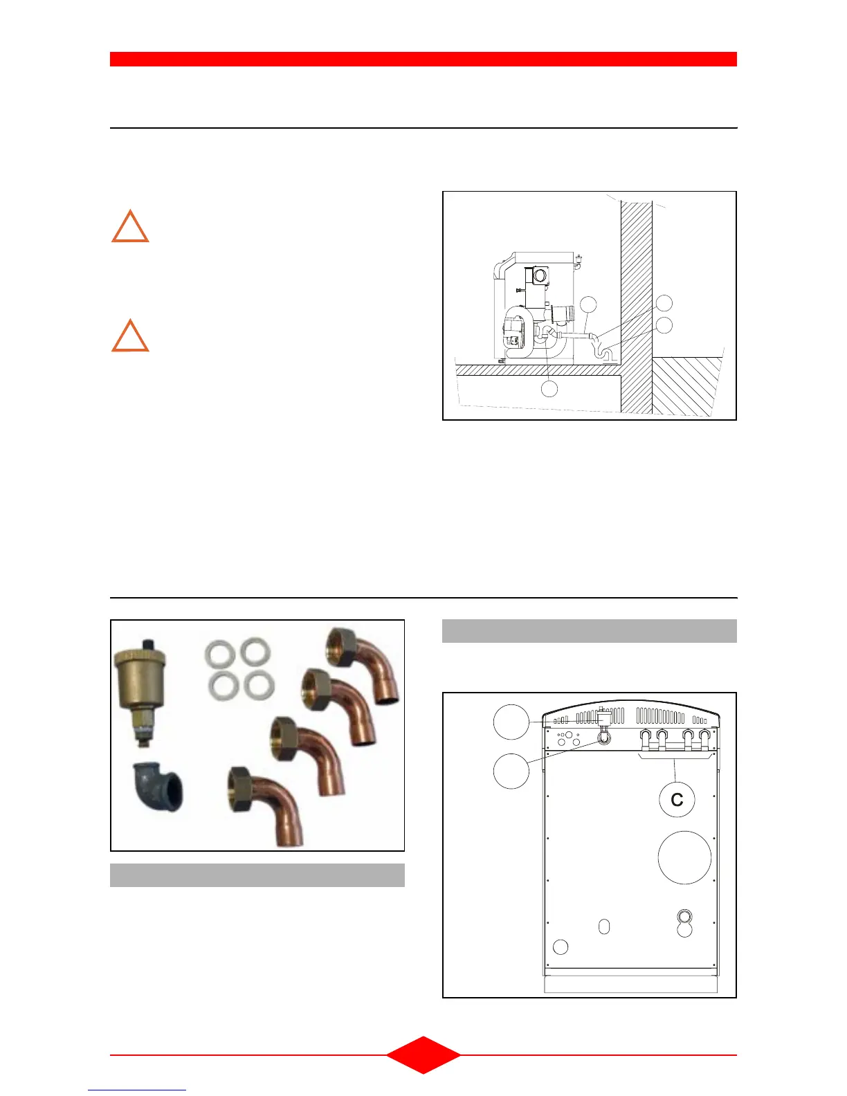
4 - CONDENSATE DRAINAGE
When connecting the condensate drain to the waste
water drain, it is essential:
- to maintain a downwards slope towards the drain,
The condensate drainage tubes must
either be buried or pass through a hea-
ted area to avoid any obstructions cau-
sed by freezing.
The condensate drainage siphon
should be checked regularly.
Before activating the boiler for the first
time, remove the condenser cover and
fill the siphon (rep 10) (
fig. 2 - page 7 -
chapter II - TECHNICAL SPECIFICA-
TIONS).
Note:
- The maximum production of condensates is
1.5
l/h (with underfloor heating low temperature
load 100 % load) which amounts to an average
daily production of 10 litres of condensates for a
15 kW installation - This low flow rate does not re
-
quire any specific treatment (extensive dilution in
the waste water). Nevertheless, if local regula
-
tions require waste to have a neutral pH, a con-
densate treatment tank must be installed
between the siphon and the waste water drain.
Accessories:
- Siphon (item no. 5)
- Tube ∅ 40 (item no. 6)
-Elbow ∅ 40 (item no. 7)
- Waste water drain (item no. 8)
5 - ASSEMBLY OF ACCESSORIES DELIVERED WITH THE BOILER
- Install the bend (A) on the weld for bleed connec-
tion - 3/4" section, boiler side,
- Install the bleed (B) on the 3/8" section of the
bend (A).
- Fit the 4 bends (C) and the related seals (D) on
the boiler outlet/return tubes.
!
!
5
6
7
8
FCX-30-0
Fig. 40
5.1 - Bleed + bend
Fig. 41
A
B
C
D
5.2 - 1" - Ø 22 bends + seal
F
 Loading...