- 7 -
TECHNICAL SPECIFICATIONS
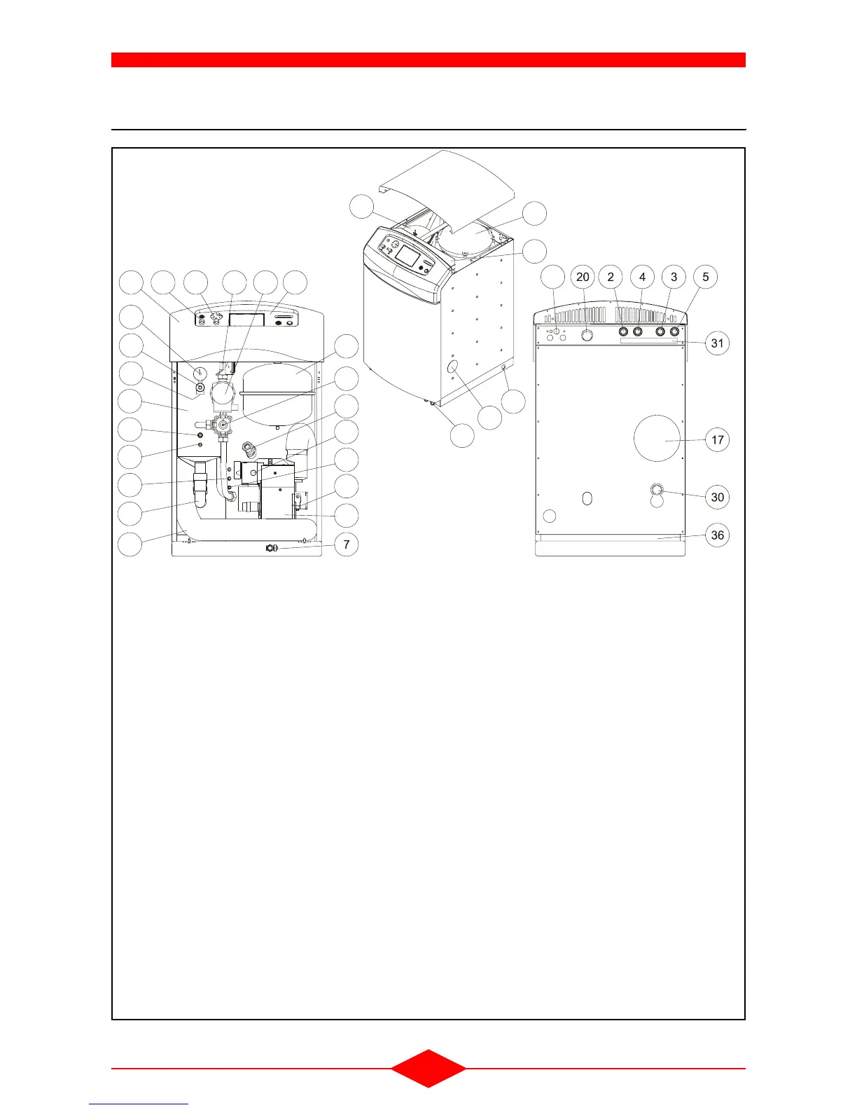
4 - DESIGNATION OF COMPONENTS
10
13
37
9
32
FCX-69-3
19
21
24
23
15
16
8
29
12
25
34
14
10
11
35
6 11828
22
26 33
27
27
Fig. 2
Front view Rear view
1) Control panel
2) 1
st
circuit heating flow
3) 1
st
circuit heating return
4) 2
nd
circui heating flow / Primary flow - (outlet of the
boiler to the domestic hot water preparation) (optio-
nal)
5) 2
nd
circuit heating return / Primary return - (return
from domestic hot water preparation to the boiler)
(optional)
6) Plastic cover
7) Drain cock
8) Oil supply
9) Terminal box protection plate
10)Condenser
11)Oil burner
12)Sight glass
13)Boiler shell
14)Pressure gauge
15)Combustion test point
16)Siphon
17)Evacuation des produits de combustion
18)Heating circulating pump
19)Safety valve
20)Weld for air bleed connection (bend + air bleed deli-
vered with the boiler)
21) Air inlet duct to the burner
22)Expansion vessel
23)Manual mixing valve
24) Safety valve outlet
25)Pocket for boiler temperature control thermostat bulb
26)Water overheating safety thermostat
27)Opening for passage of handling bars
28)Temperature thermometer bulb, heating outlet 1
st
cir-
cuit
29)Burner safety reset button
30)Condensate drain
31)Conduit for passage of 230 V cables
32)Conduit for passage of sensor cables
33)Combustion product overheating safety thermostat
34)Pocket for combustion product overheating safety
thermostat bulb
35)Pocket for water overheating safety thermostat bulb
36)Hole for oil hose raceway and outlet of the safety val-
ve
37)Hole for check or adjustment of the burner oil pump
pressure
 Loading...