21
Hardware Installation Process
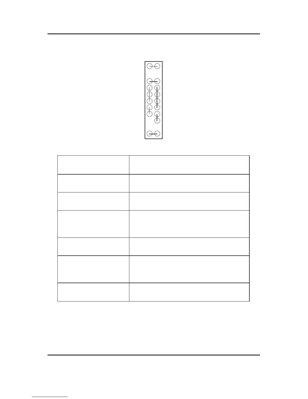
E) J7 (2x11 pins jumper)
Please connect the power LED, PC speaker, reset switch and power switch etc of your chassis front
panel to the front panel jumper according to the pin assignment above.
GN (Green Switch) Open: Normal Operation
Close: Entering Green Mode
GD (Green LED) Pin 1: LED anode(+)
Pin 2: LED cathode(-)
HD (IDE Hard Disk Active LED) Pin 1: LED anode(+)
Pin 2: LED cathode(-)
SPK (Speaker Connector) Pin 1: VCC(+)
Pin 2- Pin 3: NC
Pin 4: Data(-)
RE (Reset Switch) Open: Normal Operation
Close: Reset Hardware System
P+P-P-(Power LED) Pin 1: LED anode(+)
Pin 2: LED cathode(-)
Pin 3: LED cathode(-)
PW (Soft Power Connector) Open: Normal Operation
Close: Power On/Off
1
1
1
1
1
GN HD
SPK RE GD
P-P-P+
PW
 Loading...