EasyManua.ls Logo

Gigabyte GA-B85M-HD3 User Manual

Gigabyte GA-B85M-HD3
36 pages
To Next Page IconTo Next Page
To Previous Page IconTo Previous Page
Page #16 background imageLoading...
Page #16 background image
- 16 -
11) F_USB1/2 (USB 2.0/1.1 Headers)
The headers conform to USB 2.0/1.1 specication. Each USB header can provide two USB ports via an
optional USB bracket. For purchasing the optional USB bracket, please contact the local dealer.
Pin No. Denition Pin No. Denition
1 Power (5V) 6 USB DY+
2 Power (5V) 7 GND
3 USB DX- 8 GND
4 USB DY- 9 No Pin
5 USB DX+ 10 NC
Do not plug the IEEE 1394 bracket (2x5-pin) cable into the USB header.
Prior to installing the USB bracket, be sure to turn off your computer and unplug the power cord from the power
outlet to prevent damage to the USB bracket.
10) F_USB30 (USB 3.0/2.0 Header)
The header conforms to USB 3.0/2.0 specication and can provide two USB ports. For purchasing the
optional 3.5" front panel that provides two USB 3.0/2.0 ports, please contact the local dealer.
Pin No. Denition Pin No. Denition
1 VBUS 11 D2+
2 SSRX1- 12 D2-
3 SSRX1+ 13 GND
4 GND 14 SSTX2+
5 SSTX1- 15 SSTX2-
6 SSTX1+ 16 GND
7 GND 17 SSRX2+
8 D1- 18 SSRX2-
9 D1+ 19 VBUS
10 NC 20 No Pin
F_USB30
F_AUDIO(H)
DB_PORT
F_PANEL(NH) F_PANEL
(H61M-D2)
ACPI_CPT
(GA-IVB)
BIOS_PH
(GA-IVB)
SMB_CPT
(GA-IVB)
CLR_CMOS
CI
DIS_ME
GP15_CPT
(GA-IVB)
XDP_CPU
XDP_PCH
(GA-IVB)
TPM
w/housing
Voltage measurement module(X58A-OC)
PCIe power connector (SATA)(X58A-OC)
DIP
123
DIP
123
DIP
123
DIP
123
1
1
1
1
BIOS Switcher (X58A-OC)
PWM Switch (X58A-OC)
M_SATA
PWM Switch (SW1)(X79-UD7)
DIP
1 2 3 4 5
Voltage measurement points(G1.Sniper 3)
BIOS Switcher (SW4)
PCIe Control (Z87X-UP7)
DIP
1 2 3
4
DIP
1 2 3 4
DIP
1 2 3
4
DIP
1 2 3 4
ATX_12V_2X3
F_USB3 (Front Panel)
10
11
20
1
9) CLR_CMOS (Clear CMOS Jumper)
Use this jumper to clear the BIOS conguration and reset the CMOS values to factory defaults. To clear
the CMOS values, use a metal object like a screwdriver to touch the two pins for a few seconds.
Always turn off your computer and unplug the power cord from the power outlet before clearing the CMOS values.
After system restart, go to BIOS Setup to load factory defaults (select Load Optimized Defaults) or manually
congure the BIOS settings (refer to Chapter 2, "BIOS Setup," for BIOS congurations).
Open: Normal
Short: Clear CMOS Values
10
9
2
1
Prior to installing the USB front panel, be sure to turn off your computer and unplug the power cord from the power
outlet to prevent damage to the USB front panel.
Question and Answer IconNeed help?

Do you have a question about the Gigabyte GA-B85M-HD3 and is the answer not in the manual?

Gigabyte GA-B85M-HD3 Specifications

General IconGeneral
Non-ECCYes
Memory voltage1.5 V
Memory channelsDual-channel
Memory slots typeDIMM
Number of memory slots2
Supported memory typesDDR3-SDRAM
Maximum internal memory16 GB
Supported memory clock speeds1333, 1600 MHz
Processor socketLGA 1150 (Socket H3)
Processor manufacturerIntel
Compatible processor seriesIntel Celeron, Intel Pentium
Maximum number of SMP processors1
Power fan connectorNo
Number of SATA connectors6
Number of SATA III connectors4
HDMI version1.4a
USB 2.0 ports quantityUSB 2.0 ports have a data transmission speed of 480 Mbps, and are backwards compatible with USB 1.1 ports. You can connect all kinds of peripheral devices to them.
Audio chipRealtek ALC887
Component forPC
Power source typeATX
Motherboard chipsetIntel® B85
Audio output channels7.1 channels
Motherboard form factormini ATX
Supported storage drive interfacesSATA, SATA II, SATA III
Graphics cardHD Graphics
Maximum resolution4096 x 2160 pixels
Parallel processing technology supportNot supported
Bundled softwareIntel Rapid Start Technology\\r Intel Smart Connect Technology\\r Intel Small Business Advantage\\r Norton Internet Security
BIOS typeUEFI AMI
ACPI version2.0a
Weight and Dimensions IconWeight and Dimensions
Depth174 mm
Width244 mm

Summary

Hardware Installation

Installation Precautions

Essential safety guidelines and procedures before installing hardware components.

Product Specifications

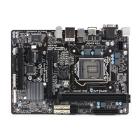
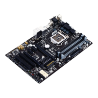
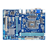
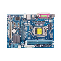
Detailed technical specifications for the motherboard and its features.

Installing the CPU

Step-by-step instructions for installing the Central Processing Unit (CPU).

Installing the Memory

Guidelines for installing RAM modules, including dual-channel configuration.

Installing Expansion Cards

Instructions for installing expansion cards into PCI Express slots.

Back Panel Connectors

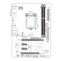
Overview of ports and connectors on the motherboard's rear panel.

Internal Connectors

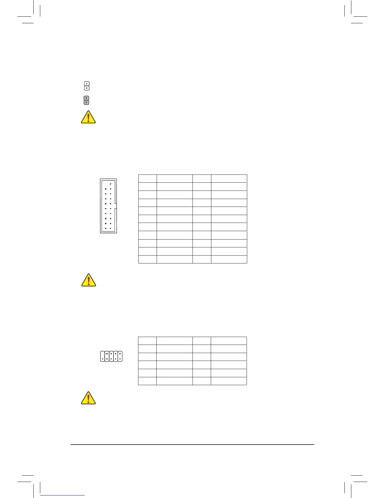
Explanation of internal headers and connectors for system components.

BIOS Setup

Startup Screen

Description of the initial boot screen and function key commands.

M.I.T.

Configuration settings for CPU, memory, and system performance tuning.

System Configuration

Settings for system language, date, time, and access levels.

BIOS Features

Configuration options for boot order, security, and system startup behavior.

Peripherals Configuration

Settings for onboard devices like graphics, audio, USB, and SATA.

Power Management Settings

Options for controlling system power states and wake-up events.

Save & Exit BIOS

Options for saving changes, loading defaults, and exiting the BIOS setup.

Drivers Installation

Regulatory Statements

Regulatory Notices

General legal notices, copyright information, and disclaimers.

Environmental Compliance

Information on RoHS, WEEE directives, and proper disposal of electronic waste.

Contact Information

GIGABYTE Global Service System

Details on accessing GIGABYTE's online technical support and service system.

Related product manuals