Appendix
0020239562_02 EASICOM 3 Installation and maintenance instructions 37
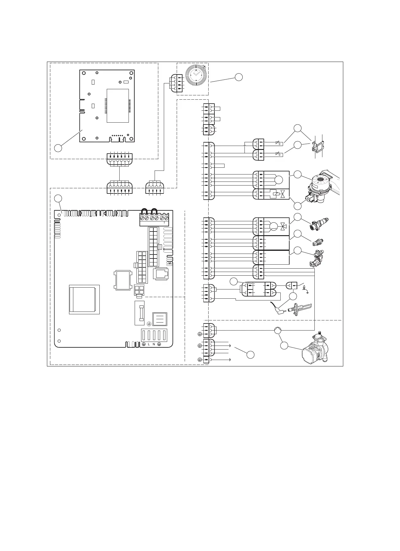
E Wiring diagram: Combi boiler
X2
X14
X21
L
N
19
10
20
2
6
3
11
13
14
18
7
17
8
X51
X51
X20
16
1
9
3
15
4
5
10
11
6
13
X51 X35
X20
X40 X51
X30
X2
X21
X41
X22
X14
L
N
–
+
24V=
RT BUS
Burner
off
RT
230Vac
X1
FUS
X106
X32
X90
X12
X35
X1
L
N
RT 230Vac
X35
4
1
3
2
eBUS
RT 24V
Burner off
X106
1
3
4
1
3
3
1
2
M
1
3
4
6
1
2
3
M
5
4
2
1
2
1
2
1
N
L
L
24V
230V~
24V
230V~
2
7
8
9
10
12
11
1
4
3
5
6
14
13
1 Main PCB
2 Interface PCB
3 Timer
4 Temperature sensor on the heating flow
5 Temperature sensor on the heating return
6 Fan
7 Gas valve assembly
8 3-port diverter valve
9 Pressure sensor
10 Flow rate sensor
11 External ignition transformer
12 Heating pump
13 Ionisation and ignition electrode
14 Main power supply and connection for 230 V control
 Loading...