22
9 Flue Preparation and Installation
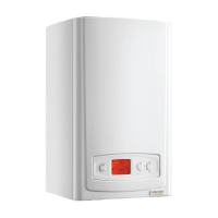
9.1 Top Horizontal Rear flue - Telescopic
Part No. A2043600. Refer to diagram 9.1 for
kit contents.
9.2 Flue Length
If a wall thickness of 232 min. to 437 max. is available the
Top horizontal rear flue - telescopic can be used without
extensions.
If the wall thickness is greater than 437 then using extensions
a maximum horizontal flue length of 8 metres plus the Top
horizontal rear flue - telescopic can be achieved. However, for
every 90
o
or
45
o
elbows used the flue length MUST be reduced
by 1 metre.
When extension pipes are used the flue system must be
designed to have a continuous fall to the boiler of at least
44mm/metre (2.5°) to allow condensate to run back into the
boiler and out via the drain.
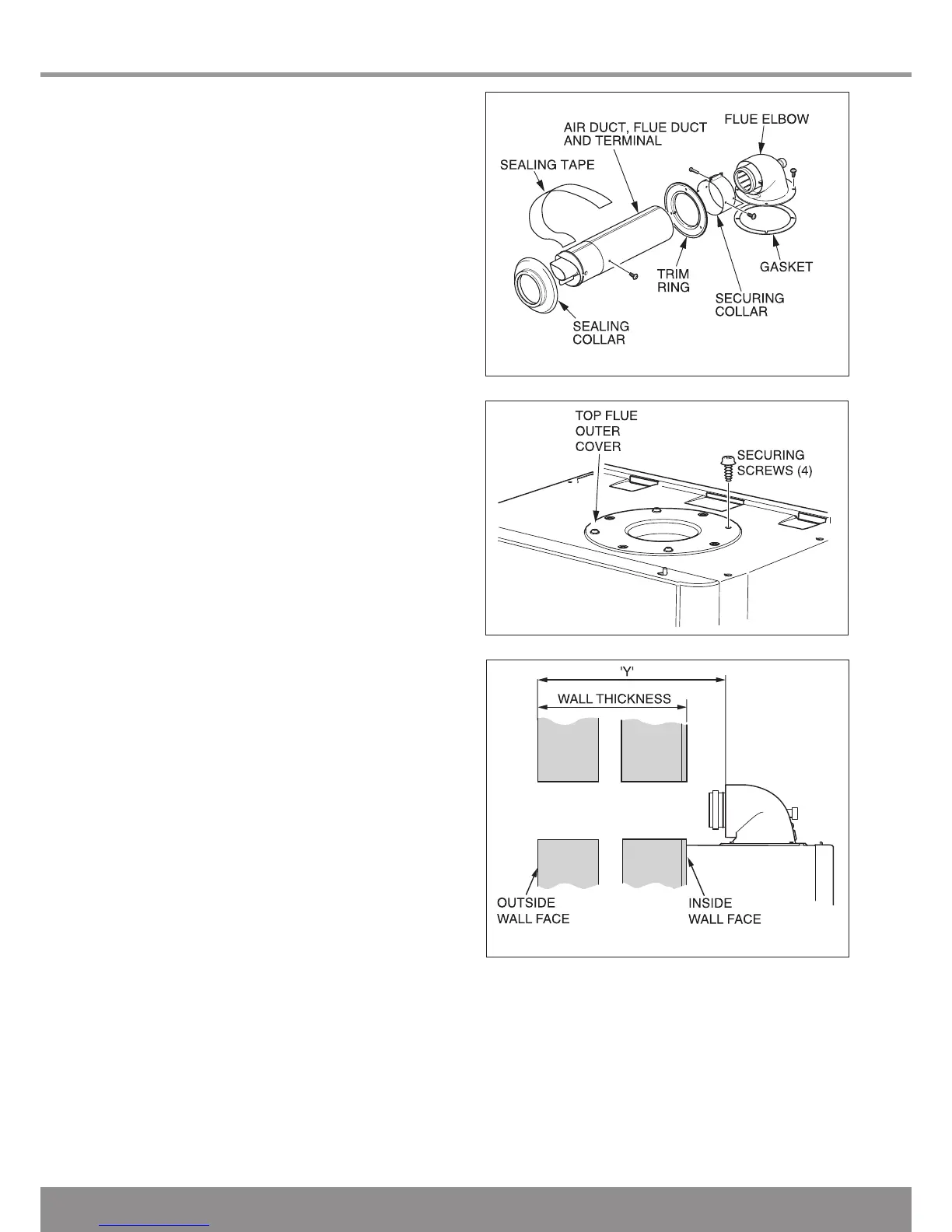
9.3 Preparation
Remove the top flue outlet cover secured with four screws,
see diagram 9.2.
Using these screws inserted into the same holes on the boiler,
tighten and secure the flue hood top, see diagram 9.3.
Temporarily fit the flue elbow, measure the distance from the
outside wall to flue elbow. If the measurement ‘Y’ exceeds
525mm, see diagram 9.3, then the appropriate length of
extension pipe is required. If the dimension is less than
320mm DO NOT cut the flue, it can project beyond the
outside wall face, see diagram 9.4. If this is not desirable then
a Top horizontal rear flue - standard MUST be used and cut to
length.
9.4 Flue Fitting
Set the flue to the required length ‘Y’, ensure the air duct
seams line up.
Remove the flue elbow.
Mark the securing hole position in the air duct. Drill a 3mm
diameter hole at this position, take care not to pierce the
inner flue duct. Secure with screw provided and tape the joint,
see diagram 9.5.
Fit the sealing collar onto the locating ring on the flue terminal,
see diagram 9.6.
Push the flue assembly into the wall, externally or internally,
until the end of the assembly protrudes a short way from the
inside face of the wall. This will enable the internal trim ring (if
required) to be positioned and allow the flue assembly to be
drawn back up to the flue elbow.
Secure the flue elbow in position on top of the boiler with four
torque headed screws supplied.
Draw the flue assembly from wall and engage the flue duct
into the elbow and butt fit between the air duct and flue elbow.
Ensure the correct alignment of the flue.
Fit the securing collar in position, mark through two of the pre
drilled holes in the securing collar. Remove securing collar
and drill two 3mm diameter holes one in the elbow and one in
the air duct, take care not to pierce the inner flue duct. Fit the
securing collar and secure with screws provided, see diagram
9.7.
Slide the internal trim ring back against the wall, securing in
place with a small amount of sealant if required.
12925
Diagram 9.1
Diagram 9.2
13016
Diagram 9.3
12806
 Loading...